3,512
Views
18
CrossRef citations to date
0
Altmetric
Original Articles

Development of a Multi-Stage Axial Flow Cyclone

, , , &
Pages 253-261 | Received 10 Jun 2009, Accepted 11 Nov 2009, Published online: 17 Feb 2010

Figures & data

TABLE 1 Dimensions of the impaction inlet and each cyclone stage of the prototype

FIG. 1 (a) Schematic diagram of the overall system of the prototype. (b) Schematic diagram of an axial flow cyclone stage (Stages #1–5). (c) Schematic diagram of the impaction inlet.
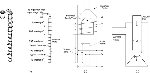
FIG. 1 (a) Schematic diagram of the overall system of the prototype. (b) Schematic diagram of an axial flow cyclone stage (Stages #1–5). (c) Schematic diagram of the impaction inlet.

FIG. 2 Schematic diagram of experimental setup for the calibration of the impaction inlet and individual cyclone stages.
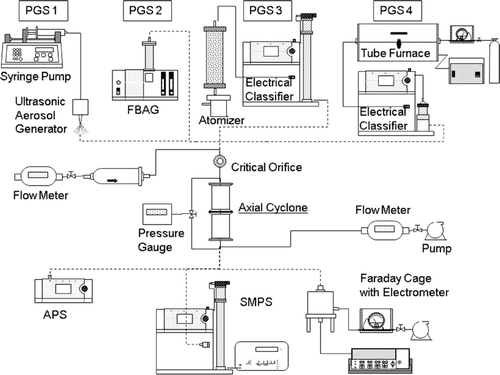
FIG. 2 Schematic diagram of experimental setup for the calibration of the impaction inlet and individual cyclone stages.

TABLE 2 Experimental setups for the individual calibration of the impaction inlet and cyclone stages

FIG. 3 Particle collection efficiency curves for the 4th cyclone stage under two different pressure conditions (i.e., 319 torr and 274 torr) at 20 lpm. (a) aerodynamic size as the abscissa; (b) square root of StK number as the abscissa.
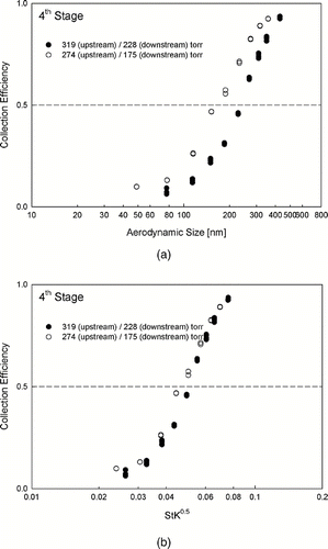
FIG. 3 Particle collection efficiency curves for the 4th cyclone stage under two different pressure conditions (i.e., 319 torr and 274 torr) at 20 lpm. (a) aerodynamic size as the abscissa; (b) square root of StK number as the abscissa.

TABLE 3 Experimental cutoff particle sizes of the impaction inlet and cyclone stages (Note that two orifice plates were installed in the assembled cyclone prototype to regulate the upstream pressures of Stages 4 and 5: one is between Stages 3 and 4 and the other between Stages 4 and 5)

FIG. 4 Measured collection efficiency curves of the impaction inlet and individual cyclone stages of the prototype.
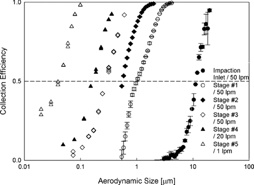
FIG. 4 Measured collection efficiency curves of the impaction inlet and individual cyclone stages of the prototype.

FIG. 5 Collection efficiency curves as a function of the particle Stokes number for all the axial flow cyclone stages of the prototype.
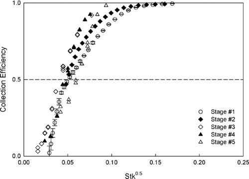
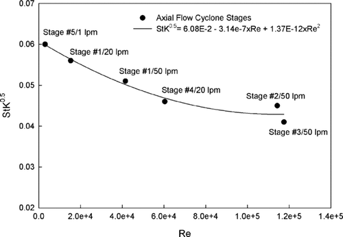
FIG. 5 Collection efficiency curves as a function of the particle Stokes number for all the axial flow cyclone stages of the prototype.
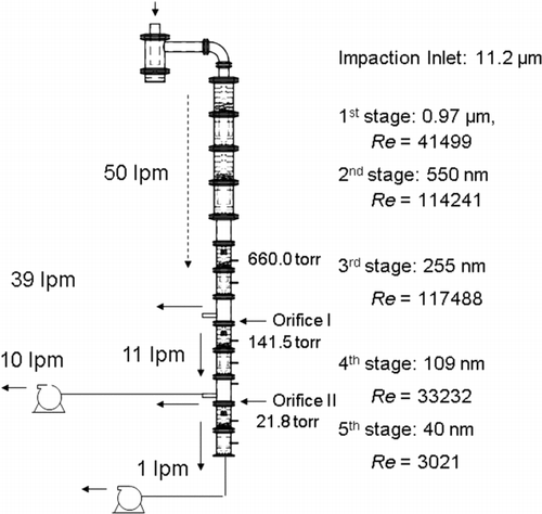
FIG. 6 Dimensionless cutoff size (StK 50 0.5) vs. flow Reynolds number for all axial flow cyclone stages.

FIG. 6 Dimensionless cutoff size (StK 50 0.5) vs. flow Reynolds number for all axial flow cyclone stages.

FIG. 7 Overall flow operation scheme of the prototype and the corresponding cutoff sizes for the impaction inlet and cyclone stages.

FIG. 7 Overall flow operation scheme of the prototype and the corresponding cutoff sizes for the impaction inlet and cyclone stages.

Reprints and Corporate Permissions

Please note: Selecting permissions does not provide access to the full text of the article, please see our help page How do I view content?

To request a reprint or corporate permissions for this article, please click on the relevant link below:

Academic Permissions

Please note: Selecting permissions does not provide access to the full text of the article, please see our help page How do I view content?

Obtain permissions instantly via Rightslink by clicking on the button below:

If you are unable to obtain permissions via Rightslink, please complete and submit this Permissions form. For more information, please visit our Permissions help page.