776
Views
4
CrossRef citations to date
0
Altmetric
Regular Articles

Design and Characterization of an Improved Screw-Assisted Rotary Feeding System for Aerosolization of Ultra-Small Quantities of Particulate Solids

, , , , , & show all
Pages 563-569 | Received 21 Dec 2009, Accepted 13 Mar 2010, Published online: 09 Jun 2010

Figures & data

FIG. 1 Design of the screw-assisted rotary feeding system: (a) front view, (b) side view.

FIG. 1 Design of the screw-assisted rotary feeding system: (a) front view, (b) side view.

FIG. 2 Experimental setup. MFC, mass flow controller; SS, stainless steel.

FIG. 2 Experimental setup. MFC, mass flow controller; SS, stainless steel.

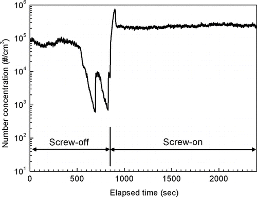
FIG. 3 Effects of the screw at the tip of the stirrer for the 12-grooved rotor at a speed of 3 rpm.

FIG. 3 Effects of the screw at the tip of the stirrer for the 12-grooved rotor at a speed of 3 rpm.

FIG. 4 Number concentrations at various rotational speeds: (a) 4-grooved rotor and (b) 12-grooved rotor.
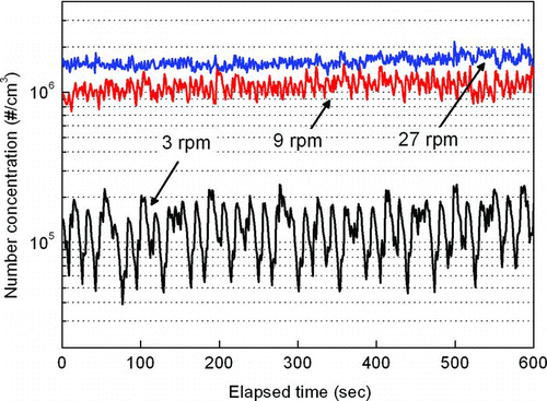
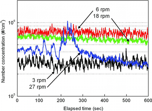
FIG. 4 Number concentrations at various rotational speeds: (a) 4-grooved rotor and (b) 12-grooved rotor.

FIG. 5 Comparison of the number concentrations for the 4- and 12-grooved rotors at a speed of 6 rpm.
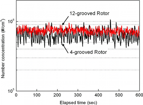
FIG. 5 Comparison of the number concentrations for the 4- and 12-grooved rotors at a speed of 6 rpm.

TABLE 1 Average number concentration and calculated COV of the 4- and 12-grooved rotors at various rotational speeds

FIG. 6 Size distribution of aerosolized sorbent particles using the 12-grooved rotor at various rotational speeds, measured by (a) APS and (b) SMPS.
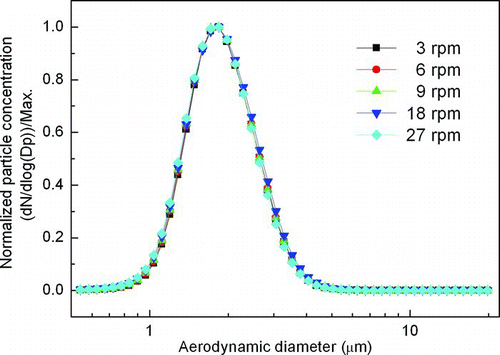
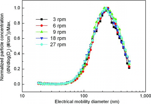
FIG. 6 Size distribution of aerosolized sorbent particles using the 12-grooved rotor at various rotational speeds, measured by (a) APS and (b) SMPS.
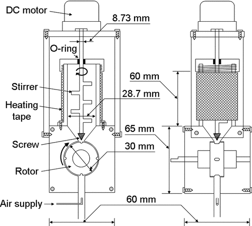
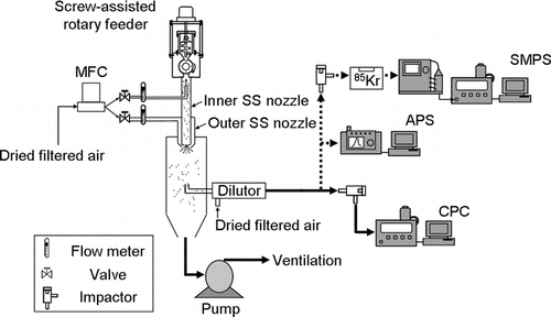
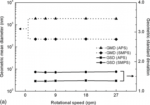
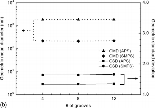
FIG. 7 GMD and GSD for (a) the 12-grooved rotor at various rotational speeds and (b) the 4-, 8-, and 12-grooved rotors at 27 rpm.

FIG. 7 GMD and GSD for (a) the 12-grooved rotor at various rotational speeds and (b) the 4-, 8-, and 12-grooved rotors at 27 rpm.

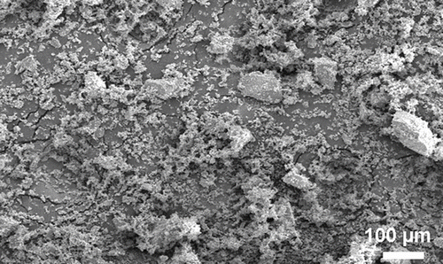
FIG. 8 Scanning electron microscopy image of the discharged sorbent particles.

FIG. 8 Scanning electron microscopy image of the discharged sorbent particles.

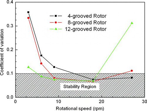
FIG. 9 Verified stability region for the 4-, 8-, and 12-grooved rotors at various rotational speeds.

FIG. 9 Verified stability region for the 4-, 8-, and 12-grooved rotors at various rotational speeds.

Reprints and Corporate Permissions

Please note: Selecting permissions does not provide access to the full text of the article, please see our help page How do I view content?

To request a reprint or corporate permissions for this article, please click on the relevant link below:

Academic Permissions

Please note: Selecting permissions does not provide access to the full text of the article, please see our help page How do I view content?

Obtain permissions instantly via Rightslink by clicking on the button below:

If you are unable to obtain permissions via Rightslink, please complete and submit this Permissions form. For more information, please visit our Permissions help page.