3,026
Views
122
CrossRef citations to date
0
Altmetric
Original Articles

The Detection Efficiency of the Single Particle Soot Photometer

, , , , , , , , , , , & show all
Pages 612-628 | Received 30 Sep 2009, Accepted 21 Mar 2010, Published online: 14 Jul 2010

Figures & data

FIG. 1 Schematic of the flame-generated soot generation and detection scheme with the filter sampler, single particle soot photometer (SP2), scanning mobility particle sizer (SMPS), condensation particle counter (CPC), Couette centrifugal particle mass analyzer (CPMA), and differential mobility analyzer (DMA).
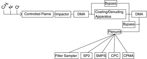
FIG. 1 Schematic of the flame-generated soot generation and detection scheme with the filter sampler, single particle soot photometer (SP2), scanning mobility particle sizer (SMPS), condensation particle counter (CPC), Couette centrifugal particle mass analyzer (CPMA), and differential mobility analyzer (DMA).

FIG. 2 Schematic of the Single Particle Soot Photometer (SP2) following CitationSchwarz et al. (2006). The sample aerosol is confined with filtered sheath flow to the center 1/4 of the laser beam, and then drawn out of the laser cavity through the exhaust line. Although drawn in the page for simplicity, the sample line and exhaust lines extend perpendicular to the detection axes (i.e., vertically into and out of the page).
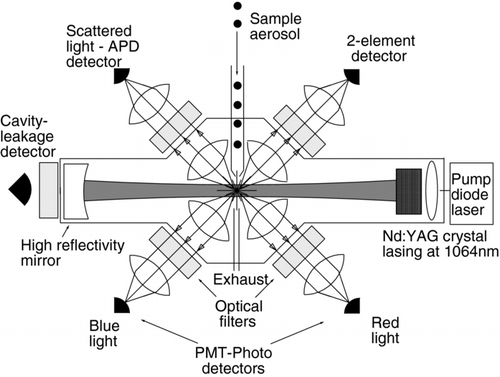
FIG. 2 Schematic of the Single Particle Soot Photometer (SP2) following CitationSchwarz et al. (2006). The sample aerosol is confined with filtered sheath flow to the center 1/4 of the laser beam, and then drawn out of the laser cavity through the exhaust line. Although drawn in the page for simplicity, the sample line and exhaust lines extend perpendicular to the detection axes (i.e., vertically into and out of the page).

TABLE 1 Peak scattered laser power incident on the SP2 detector from polystyrene latex spheres (PSLs). Values are normalized to the power from 220-nm PSL particles (refractive index = 1.59, 0).

FIG. 3 Comparison of the measurement of laser intensity based on measurements inside and outside the cavity. The latter is measured with the laser leakage photodetector. The former is measured as the most probable peak power incident on the SP2 scatter detector when a polystyrene latex sphere (PSL) of known diameter and index of refraction is sampled (see text). The power in the laser cavity was varied by changing the amount of pump laser light incident on the Nd:YAG crystal.
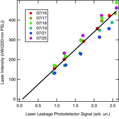
FIG. 3 Comparison of the measurement of laser intensity based on measurements inside and outside the cavity. The latter is measured with the laser leakage photodetector. The former is measured as the most probable peak power incident on the SP2 scatter detector when a polystyrene latex sphere (PSL) of known diameter and index of refraction is sampled (see text). The power in the laser cavity was varied by changing the amount of pump laser light incident on the Nd:YAG crystal.

FIG. 4 Top: SP2 peak height distribution for typical sample of FGS aerosol used to in the analysis here. Bottom: the SMPS distribution for the same FGS sample. The shaded sections represent the selected peak height and diameter ranges, respectively, for the primary aerosol mode for which SP2 detection efficiency was calculated.
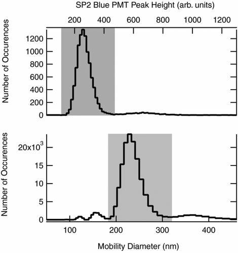
FIG. 4 Top: SP2 peak height distribution for typical sample of FGS aerosol used to in the analysis here. Bottom: the SMPS distribution for the same FGS sample. The shaded sections represent the selected peak height and diameter ranges, respectively, for the primary aerosol mode for which SP2 detection efficiency was calculated.

FIG. 5 Comparison of the number concentration as measured with the SP2 and the CPC sampling the same FSG aerosol during an experimental dataset. A time delay occurs between the SP2 and CPC sampling due to different sample line lengths and other differences. The time delay, identified by matching their time resolved concentrations, has already been included here so there is no apparent time offset. FSG number concentrations during a series of measurements typically varied approximately at the level shown here or somewhat less. The color scale indicates SP2 laser intensity—at low intensity detection efficiency decreases.
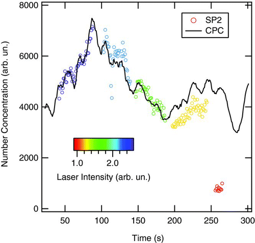
FIG. 5 Comparison of the number concentration as measured with the SP2 and the CPC sampling the same FSG aerosol during an experimental dataset. A time delay occurs between the SP2 and CPC sampling due to different sample line lengths and other differences. The time delay, identified by matching their time resolved concentrations, has already been included here so there is no apparent time offset. FSG number concentrations during a series of measurements typically varied approximately at the level shown here or somewhat less. The color scale indicates SP2 laser intensity—at low intensity detection efficiency decreases.

FIG. 6 Laser-cavity leakage as measured with a photodetector as a function of the current driven through the solid-state pump laser. Each data point is the value averaged over a single experimental setup and laser intensity tested (∼ 850 points).
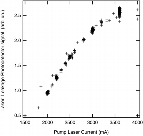
FIG. 6 Laser-cavity leakage as measured with a photodetector as a function of the current driven through the solid-state pump laser. Each data point is the value averaged over a single experimental setup and laser intensity tested (∼ 850 points).

TABLE 2 The range of values of various experimental parameters explored in this study. Aerosol generated from 94 unique configurations of these parameters was sampled at five different SP2 laser intensities

FIG. 7 Probability distributions of color ratios measured at different laser intensities. Ambient pressure was ∼1000 hPa. (a) Color ratios for 2-fg FSG particles coated with dioctyl sebacate to form a total particle mass of 4.5 fg. (b) color ratios for ambient rBC-containing aerosol measured during the Texas Air Quality study (CitationSchwarz et al. 2008a) at pressures > 900 hPa. Laser intensity is expressed in units of power (nW) detected due to scattering by 220-nm PSLs (see text). The relative gain in the red and blue channel detectors is chosen such that the color ratio associated with rBC is 1. The higher variability in the low intensity case in ambient aerosol is caused by the reduced statistical ensemble of rBC particles detected during the short time intervals of reduced laser intensity.
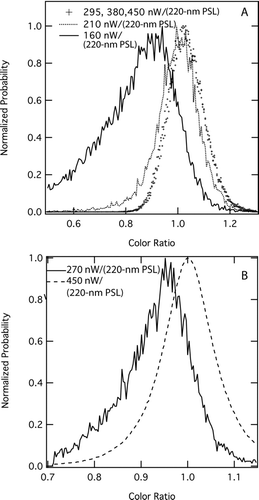
FIG. 7 Probability distributions of color ratios measured at different laser intensities. Ambient pressure was ∼1000 hPa. (a) Color ratios for 2-fg FSG particles coated with dioctyl sebacate to form a total particle mass of 4.5 fg. (b) color ratios for ambient rBC-containing aerosol measured during the Texas Air Quality study (CitationSchwarz et al. 2008a) at pressures > 900 hPa. Laser intensity is expressed in units of power (nW) detected due to scattering by 220-nm PSLs (see text). The relative gain in the red and blue channel detectors is chosen such that the color ratio associated with rBC is 1. The higher variability in the low intensity case in ambient aerosol is caused by the reduced statistical ensemble of rBC particles detected during the short time intervals of reduced laser intensity.

FIG. 8 Probability distributions of thermal radiation peak heights measured at different laser intensities for 2-fg FGS particles coated with dioctyl sebacate to form 4.5 fg total mass at 1000 hPa. Laser intensity is expressed in units of nW/(220-nm PSL), as described in the text. The histogram at the highest intensity was fit with a Gaussian function (black line), which is superposed on each of the lower intensity histograms as a guide to the eye. The histograms are normalized to the same number of particles.
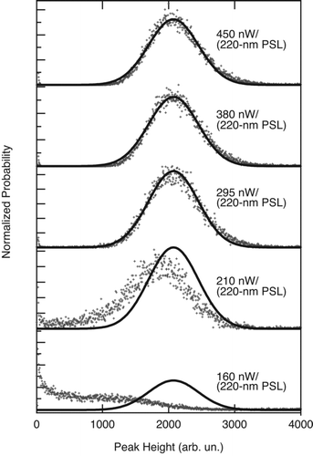
FIG. 8 Probability distributions of thermal radiation peak heights measured at different laser intensities for 2-fg FGS particles coated with dioctyl sebacate to form 4.5 fg total mass at 1000 hPa. Laser intensity is expressed in units of nW/(220-nm PSL), as described in the text. The histogram at the highest intensity was fit with a Gaussian function (black line), which is superposed on each of the lower intensity histograms as a guide to the eye. The histograms are normalized to the same number of particles.

FIG. 9 SP2 detection efficiency (SPE) as a function of laser intensity for different FSG mass pairs of nascent and denuded particles measured at 1000 hPa. All the samples are from flames with equivalence ratio (ϕ) of 2.1. Particle masses are given in the legend as determined by the CPMA. Open symbols represent nascent soot particles, which have a non-refractory component. For each pair, the solid symbols represent the nascent aerosol denuded of non-refractory component. The denuded values are fit with Hill functions as a guide to the eye.
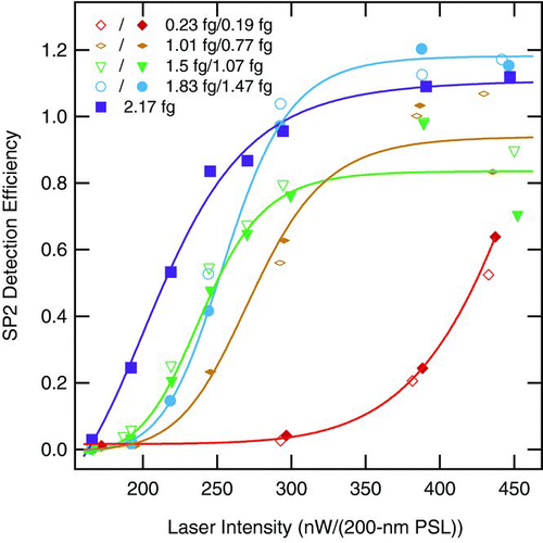
FIG. 9 SP2 detection efficiency (SPE) as a function of laser intensity for different FSG mass pairs of nascent and denuded particles measured at 1000 hPa. All the samples are from flames with equivalence ratio (ϕ) of 2.1. Particle masses are given in the legend as determined by the CPMA. Open symbols represent nascent soot particles, which have a non-refractory component. For each pair, the solid symbols represent the nascent aerosol denuded of non-refractory component. The denuded values are fit with Hill functions as a guide to the eye.

FIG. 10 Average SP2 detection efficiency for FSG generated with an equivalence ratio (ϕ) of 1.9, size selected with a DMA, and then coated with increasing thicknesses of sulfuric acid. The total-particle masses of the denuded rBC-core particles and coated particles as noted in the legend were determined with the CPMA. The denuded core mass was 1.9 ± 0.1 fg. Particles were sampled at 1000 hPa.
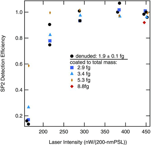
FIG. 10 Average SP2 detection efficiency for FSG generated with an equivalence ratio (ϕ) of 1.9, size selected with a DMA, and then coated with increasing thicknesses of sulfuric acid. The total-particle masses of the denuded rBC-core particles and coated particles as noted in the legend were determined with the CPMA. The denuded core mass was 1.9 ± 0.1 fg. Particles were sampled at 1000 hPa.

FIG. 11 Dependence of SP2 detection efficiency (SDE) on rBC-core mass, coating mass, and laser power measured at 1000 hPa for flame-generated soot. Bottom: SDE as a function of non-refractory coatings mass and rBC mass. Data points represent SDE for the experiments in which the denuded rBC-core mass (horizontal axis) was determined with the centrifugal particle mass analyzer (CPMA). The non-refractory coating mass (vertical axis) was determined by subtracting the denuded mass from the total particle mass as measured with the CPMA. Non-refractory mass was given a minimum value of 0.01 fg to allow plotting on a logarithmic scale. Points are colored by SP2 detection efficiency as shown in the legend. Top: The average detection efficiencies in each rBC mass-bin for each laser intensity shown in the legend. Whiskers represent the standard deviation of the values in each mass bin. The top axis shows volume-equivalent diameter (assuming 2 g/cc void-free density for rBC) that corresponds to denuded rBC-core mass on the bottom horizontal scale.
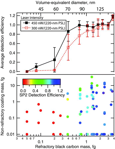
FIG. 11 Dependence of SP2 detection efficiency (SDE) on rBC-core mass, coating mass, and laser power measured at 1000 hPa for flame-generated soot. Bottom: SDE as a function of non-refractory coatings mass and rBC mass. Data points represent SDE for the experiments in which the denuded rBC-core mass (horizontal axis) was determined with the centrifugal particle mass analyzer (CPMA). The non-refractory coating mass (vertical axis) was determined by subtracting the denuded mass from the total particle mass as measured with the CPMA. Non-refractory mass was given a minimum value of 0.01 fg to allow plotting on a logarithmic scale. Points are colored by SP2 detection efficiency as shown in the legend. Top: The average detection efficiencies in each rBC mass-bin for each laser intensity shown in the legend. Whiskers represent the standard deviation of the values in each mass bin. The top axis shows volume-equivalent diameter (assuming 2 g/cc void-free density for rBC) that corresponds to denuded rBC-core mass on the bottom horizontal scale.

FIG. 12 Dependence of modal peak height and signal length as a function of laser intensity for the thermal emission from rBC particles. Values associated with small, 2 fg FGS particles coated with dioctyl sebacate to form 4.5 fg total mass are shown on the left axes. Values associated with large 26 fg fullerene particles are shown on the right axes. Top: Length of time that the blue channel signal associated with an rBC particle persisted above background noise, plotted as a function of laser intensity. Bottom: the modal peak heights associated with both particle sizes. The arbitrary units are not the same between the left-hand (4.5 fg) and right-hand (26 fg) axes. Measurements were made at 1000 hPa.
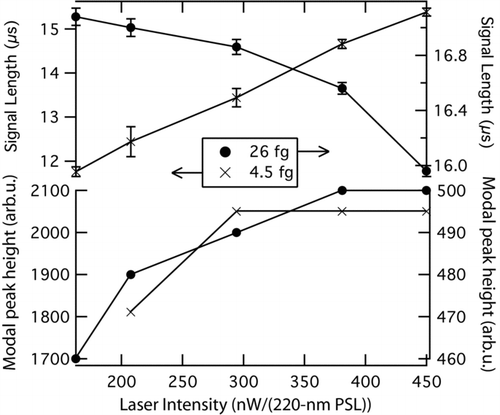
FIG. 12 Dependence of modal peak height and signal length as a function of laser intensity for the thermal emission from rBC particles. Values associated with small, 2 fg FGS particles coated with dioctyl sebacate to form 4.5 fg total mass are shown on the left axes. Values associated with large 26 fg fullerene particles are shown on the right axes. Top: Length of time that the blue channel signal associated with an rBC particle persisted above background noise, plotted as a function of laser intensity. Bottom: the modal peak heights associated with both particle sizes. The arbitrary units are not the same between the left-hand (4.5 fg) and right-hand (26 fg) axes. Measurements were made at 1000 hPa.

Reprints and Corporate Permissions

Please note: Selecting permissions does not provide access to the full text of the article, please see our help page How do I view content?

To request a reprint or corporate permissions for this article, please click on the relevant link below:

Academic Permissions

Please note: Selecting permissions does not provide access to the full text of the article, please see our help page How do I view content?

Obtain permissions instantly via Rightslink by clicking on the button below:

If you are unable to obtain permissions via Rightslink, please complete and submit this Permissions form. For more information, please visit our Permissions help page.