1,035
Views
24
CrossRef citations to date
0
Altmetric
Regular Articles

Filtration of Multi-Walled Carbon Nanotube Aerosol by Fibrous Filters

, , , &
Pages 734-740 | Received 05 Oct 2009, Accepted 17 Mar 2010, Published online: 13 Jul 2010

Figures & data

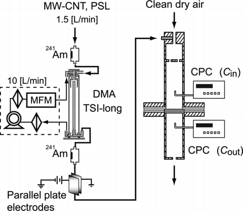
FIG. 1 Schematic diagram for the preparation of test aerosol of MWCNT.

FIG. 1 Schematic diagram for the preparation of test aerosol of MWCNT.

FIG. 2 Electrical mobility size distribution of generated aerosol with changing concentration of MWCNT-water suspension.
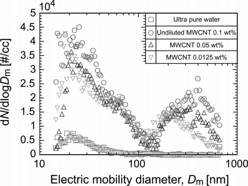
FIG. 2 Electrical mobility size distribution of generated aerosol with changing concentration of MWCNT-water suspension.

FIG. 3 Typical SEM image of generated polydisperse aerosol.

FIG. 3 Typical SEM image of generated polydisperse aerosol.

FIG. 4 The measured length, Lf of individual fibrous particles plotted against corresponding diameter, Df .
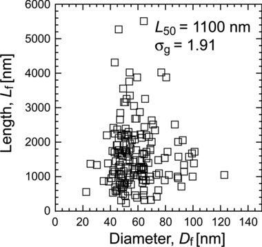
FIG. 4 The measured length, Lf of individual fibrous particles plotted against corresponding diameter, Df .

FIG. 5 Scanning electron micrographs of DMA-classified particles with the mobility diameters of (a) 100, (b) 200, and (c) 300 nm.
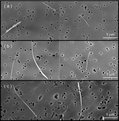
FIG. 5 Scanning electron micrographs of DMA-classified particles with the mobility diameters of (a) 100, (b) 200, and (c) 300 nm.

FIG. 6 Length distribution of DMA-classified MWCNT particles obtained from SEM images. The mobility diameters are (a) 100, (b) 200, and (c) 300 nm.
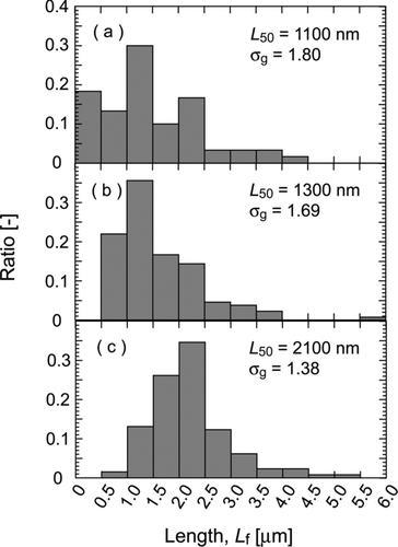
FIG. 6 Length distribution of DMA-classified MWCNT particles obtained from SEM images. The mobility diameters are (a) 100, (b) 200, and (c) 300 nm.

FIG. 7 Distributions of Heywood diameter of DMA-classified particles. The mobility diameters are (a) 100, (b) 200, and (c) 300 nm.
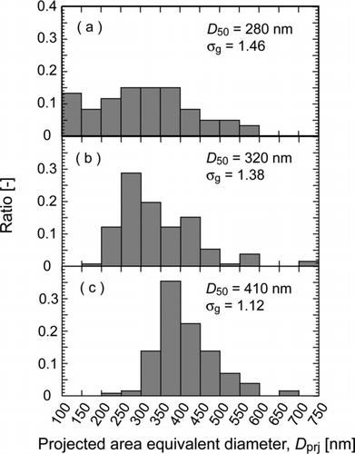
FIG. 7 Distributions of Heywood diameter of DMA-classified particles. The mobility diameters are (a) 100, (b) 200, and (c) 300 nm.

TABLE 1 Characteristics of DMA-classified MWCNT particles

FIG. 8 Experimental set up for measuring filtration efficiency.

FIG. 8 Experimental set up for measuring filtration efficiency.

FIG. 9 Penetration curves of (a) MWCNT particles and (b) spherical PSL particles through medium performance filter. The solid lines are experimental curves.
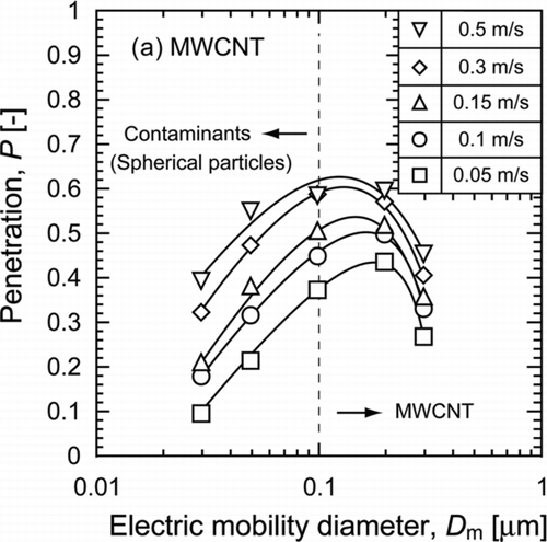
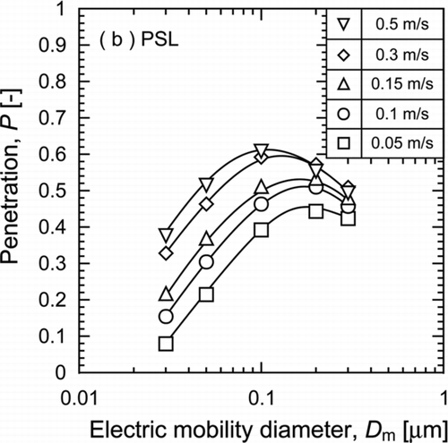
FIG. 9 Penetration curves of (a) MWCNT particles and (b) spherical PSL particles through medium performance filter. The solid lines are experimental curves.

FIG. 10 Single fiber capturing efficiencies of fibrous particles with those predicted by interception.
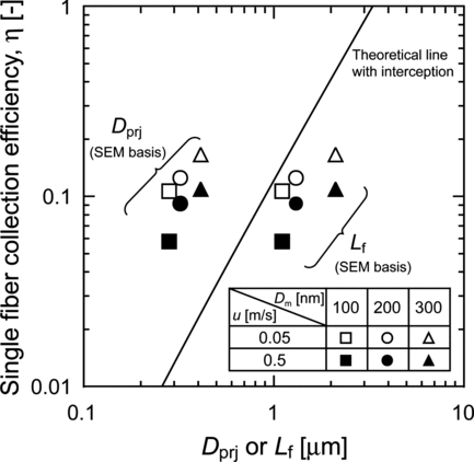
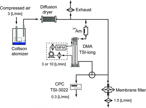
FIG. 10 Single fiber capturing efficiencies of fibrous particles with those predicted by interception.
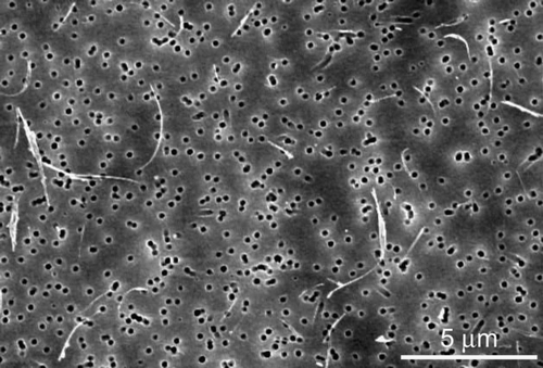
TABLE 2 Orientation angle, θ, obtained by fitting the experimental data

Supplemental material

uast_a_487881_sup_14325016.zip

Download Zip (40.4 KB)

Reprints and Corporate Permissions

Please note: Selecting permissions does not provide access to the full text of the article, please see our help page How do I view content?

To request a reprint or corporate permissions for this article, please click on the relevant link below:

Academic Permissions

Please note: Selecting permissions does not provide access to the full text of the article, please see our help page How do I view content?

Obtain permissions instantly via Rightslink by clicking on the button below:

If you are unable to obtain permissions via Rightslink, please complete and submit this Permissions form. For more information, please visit our Permissions help page.