Figures & data
FIG. 1 Schematic diagram of the experimental apparatus. (a) Aerosol generation by nebulization, adjustment of aerosol RH in Nafion 1 to high RH, drying of aerosol RH in the laminar-flow tube (see also panel b), selection of particle mobility diameter by nDMA, and measurement of activated CCN fraction. (b) Illustration of the drying of the aerosol flow by radial water-vapor diffusion into the sheath flow and the subsequent crystallization of the particles in the aerosol flow. The circles with solid dots represent spherical solution drops in a humid core flow, and the solid cubes represent the crystallized particles in a core flow. The dynamic shape factor of these cubes depends on the drying rate. Key: CCNC, cloud condensation nucleus counter; CPC, condensation particle counter; nDMA, nano differential mobility analyzer; MFC, mass flow controllers; PID, proportional integral derivative controller; PT, pressure transducer; RHS, relative humidity sensor.
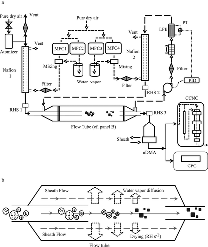
TABLE 1 Calculated drying rates in the laminar-flow tube for experimental conditions 1 to 4 employed in this study. The initial aerosol RH (i.e., core flow) and the initial sheath RH (i.e., outer flow) of each experimental condition are shown. The final column shows the calculated average drying rate at an aerosol RH of 45% (i.e., the efflorescence RH of NaCl particles; cf. Equation (EquationB4)). The drying rates are shown as open circles in panel d of
FIG. 2 Transmission electron micrographs for NaCl particles prepared at different drying rates. Images are shown for particles collected by DMA classification at 25-, 40-, and 65-nm dry mobility diameter (+1 charge). Slow and fast drying refers to experiments 1 and 4 of (i.e., 5.5 ± 0.9 and 101 ± 3 RH s–1, respectively). Images within one diameter classification are on the same scale; images between diameter classifications are scaled for a common display size.
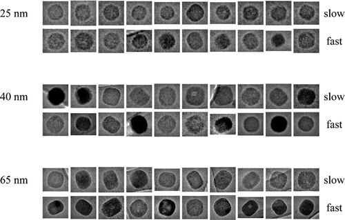
FIG. 3 CCN activation curves at 0.5% supersaturation for NaCl particles for four different drying rates at ERH (cf. ). The lines passing through the data are sigmoidal fits. The mobility-equivalent critical diameter is the intersection of a fit curve with the dashed line drawn at an activated fraction of 0.5. For comparison, the mass-equivalent critical diameter of a NaCl particle active at 0.5% supersaturation is 35.7 nm. Indicated by arrows are the mobility-equivalent critical diameters expected for NaCl particles having dynamic shape factors χ of 1.00, 1.08, and 1.24.
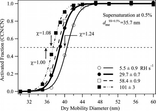
FIG. 4 CCN activation curves for supersaturations ranging from 0.15 to 1.0%. The drying rate is held constant at 29.7 ± 0.7 RH s–1 at ERH. For orientation, the thick line in this figure is the same as shown in .
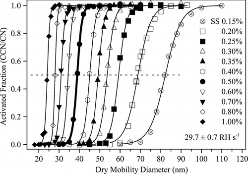
FIG. 5 (a) Dynamic shape factors χ of NaCl particles having dry mobility diameters from 23 to 84 nm and prepared by drying rates ranging from 5.5 ± 0.9 to 101 ± 3 RH s–1at ERH (cf. ). (b) Same as panel a but plotted as the inferred aqueous diameter prior to drying (i.e., by obtaining m p dry from S c and then d ve aq from m p dry for the initial RH values of ). Uncertainty is based on the standard deviation of repeated measurements made on different days for nominally identical conditions (cf. Figure S3). Lines show the expected shape factors χ c , χ fm , and χ t of cubes in the continuum, free-molecule, and transition regimes, respectively (CitationDeCarlo et al. 2004; CitationBiskos et al. 2006c). For orientation, the arrow marks the data point corresponding to the thick line shown in and .
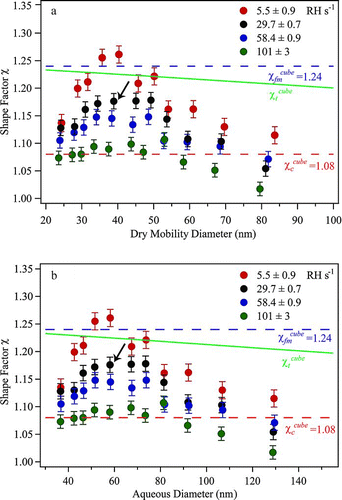
FIG. 6 Dynamic shape factors χ of NaCl particles for increasing drying rate at ERH. Results are shown for particles having mass-equivalent diameters ranging from 22.7 to 65.2 nm. The lines are not model fits but are drawn to aid the eye. Uncertainty on the data points is as described for . For orientation, the arrow marks the data point corresponding to the thick line shown in and .
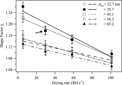
TABLE 2 Summary of the dynamic shape factors reported in the literature and those measured in this study for NaCl particles
TABLE A1 Coefficients of m p dry[S c ] for Equation (EquationA2) that parameterize the dependence of dry particle mass m p dry (kg) on critical supersaturation S c (%) for sodium chloride and ammonium sulfate at 298 K and 304 K. For S c ranging from 0.1 to 2.0%, the parameterization describes m p drywithin a multiplicative factor of 1.003 compared to the original equation (i.e., Equation (EquationA1)). The AP3 model of CitationRose et al. (2008) was used to generate the primary data used in the parameterization
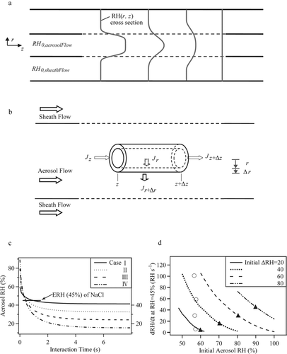
FIG. B1 Drying rate. (a) Depiction of the RH profiles in the inner and outer flows along the longitudinal axis of the flow tube. Flow is from left to right. The lighter solid lines represent the cross section of RH profile along the interaction distance and the dashed lines show the interaction area for inner and outer flows. (b) Depiction of a volume element for calculating the drying rate in the aerosol flow. (c) Calculated RH in the aerosol flow for increasing interaction time. Results are shown for the four model cases specified in . The interaction time can be related to the longitudinal position z in the flow tube by use of the linear flow velocity. The arrow indicates the ERH of NaCl particles (i.e., 45%). The slope of the curve at this point is the drying rate (RH s–1) for an aerosol RH of 45%. (d) Drying rate (RH s–1) at an aerosol RH of 45% for variable initial aerosol RH. Results are shown for several different initial Δ RH between the aerosol RH and the sheath RH. Lines show the ranges of drying rates that can be obtained by varying the initial RH but holding constant initial Δ RH. The solid triangles correspond to the four model case listed in Table B1, and the open circles indicate the calculated drying rates for the experimental conditions listed in .