2,442
Views
157
CrossRef citations to date
0
Altmetric
Original Articles

Consistency and Traceability of Black Carbon Measurements Made by Laser-Induced Incandescence, Thermal-Optical Transmittance, and Filter-Based Photo-Absorption Techniques

, , , , , , & show all
Pages 295-312 | Received 03 Mar 2010, Accepted 12 Oct 2010, Published online: 09 Jun 2011

Figures & data

FIG. 1 Experimental setup for the measurement of the size distributions of organic aerosols with or without the heated inlet. Total numbers of particles were measured by a CPC after size selection by a DMA.

FIG. 1 Experimental setup for the measurement of the size distributions of organic aerosols with or without the heated inlet. Total numbers of particles were measured by a CPC after size selection by a DMA.

TABLE 1 Summary of the measurement techniques for BC mass concentration used in this study

TABLE 2 Summary of the variable symbols and acronyms used in this study

TABLE 3 Ratios of the volumes of organic particles downstream of the heated (400°C) and unheated inlets (heated/unheated) for different mobility diameters

FIG. 2 Changes in the number size distributions of organic aerosols with changes in the temperature of the inlet (300° and 400°C) for organic species.
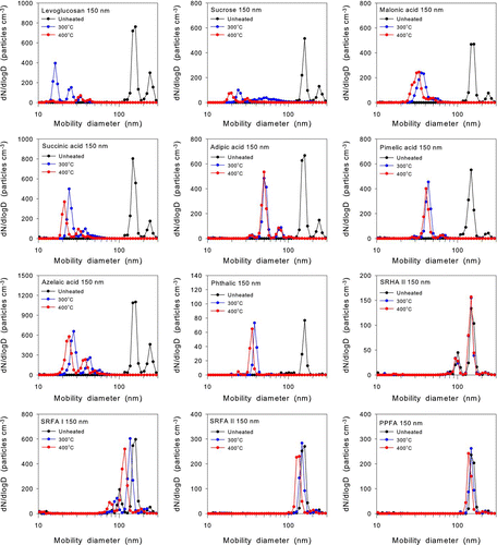
FIG. 2 Changes in the number size distributions of organic aerosols with changes in the temperature of the inlet (300° and 400°C) for organic species.

FIG. 3 Experimental setup for the calibration of the SP2 using ambient BC and commercially available BC particles. The particles were mass selected by means of an APM.

FIG. 3 Experimental setup for the calibration of the SP2 using ambient BC and commercially available BC particles. The particles were mass selected by means of an APM.

FIG. 4 Relationship between the LII peak intensity measured by the SP2 and the BC masses of ambient BC and fullerene soot.
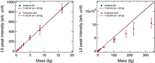
FIG. 4 Relationship between the LII peak intensity measured by the SP2 and the BC masses of ambient BC and fullerene soot.

FIG. 5 Thermograms of the HULIS obtained in the laboratory.

FIG. 5 Thermograms of the HULIS obtained in the laboratory.

TABLE 4 Summary of thermograms of organic species standards. The data for levoglucosan, pimelic acid, and azelaic acid were taken from CitationMiyazaki et al. (2007)

FIG. 6 Experimental setup for the measurement of the absorption coefficient of organic aerosols by means of two COSMOS instruments. COSMOS I was mounted downstream of a heater, and COSMOS II was operated without a heater. Total numbers of particles were measured by a CPC after size selection by a DMA.

FIG. 6 Experimental setup for the measurement of the absorption coefficient of organic aerosols by means of two COSMOS instruments. COSMOS I was mounted downstream of a heater, and COSMOS II was operated without a heater. Total numbers of particles were measured by a CPC after size selection by a DMA.

FIG. 7 Plots of equivalent mass concentrations of BC measured by COSMOS with an inlet heated to 300°C and 400°C and without a heated inlet versus the volume concentrations of organic species. The equivalent mass concentrations of BC were derived from the observed absorption coefficients by assuming a mass absorption cross section of 5.4 m2 g–1.
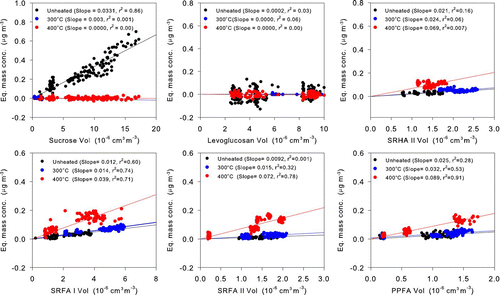
FIG. 7 Plots of equivalent mass concentrations of BC measured by COSMOS with an inlet heated to 300°C and 400°C and without a heated inlet versus the volume concentrations of organic species. The equivalent mass concentrations of BC were derived from the observed absorption coefficients by assuming a mass absorption cross section of 5.4 m2 g–1.

TABLE 5 Slopes of correlation plots of equivalent BC mass concentrations versus volume concentration measured by COSMOS I (heated inlet) and COSMOS II (without heated inlet)

TABLE 6 R 300 (OC5) and R 400 (OC5) of HULIS

TABLE 7 PC/BC ratios at different locations in Asia

FIG. 8 Daily averaged number and mass size distributions of black carbon measured by SP2 in Tokyo in August and September 2009.
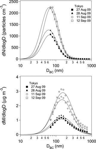
FIG. 8 Daily averaged number and mass size distributions of black carbon measured by SP2 in Tokyo in August and September 2009.

FIG. 9 Frequency distribution of the CMD and MMD of the lognormal size distributions fitted to 1-min averaged BC mass size distributions measured by SP2.
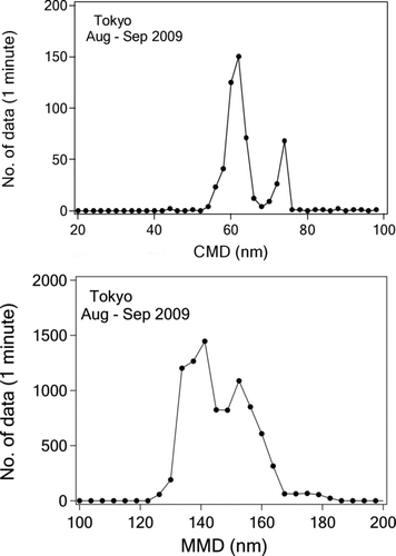
FIG. 9 Frequency distribution of the CMD and MMD of the lognormal size distributions fitted to 1-min averaged BC mass size distributions measured by SP2.

FIG. 10 Frequency distribution of the shell/core (D p/D BC) ratios of BC particles with different D BC size ranges.
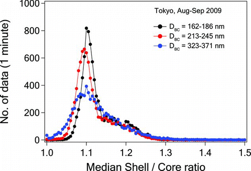
FIG. 10 Frequency distribution of the shell/core (D p/D BC) ratios of BC particles with different D BC size ranges.

FIG. 11 Time series plots of BC mass concentrations measured by SP2 and COSMOS, their ratios, and MMD in Tokyo from September 10 to September 12, 2009. The mass concentration of BC was derived from the observed absorption coefficients by assuming a mass absorption cross section of 5.4 m2 g–1.
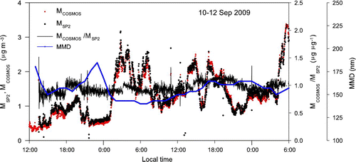
FIG. 11 Time series plots of BC mass concentrations measured by SP2 and COSMOS, their ratios, and MMD in Tokyo from September 10 to September 12, 2009. The mass concentration of BC was derived from the observed absorption coefficients by assuming a mass absorption cross section of 5.4 m2 g–1.

FIG. 12 Correlation plots of BC mass concentrations measured by SP2 and those measured by COSMOS in 2009 using 1-min average data (left panel) and 1-h average data (right panel). Mass concentration of BC by COSMOS was derived from the absorption coefficients by assuming a mass absorption cross section of 5.4 m2 g–1. The least squares fitted line is denoted as the solid line.
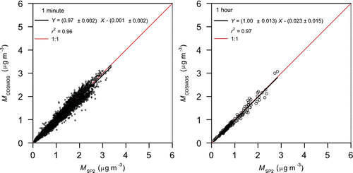
FIG. 12 Correlation plots of BC mass concentrations measured by SP2 and those measured by COSMOS in 2009 using 1-min average data (left panel) and 1-h average data (right panel). Mass concentration of BC by COSMOS was derived from the absorption coefficients by assuming a mass absorption cross section of 5.4 m2 g–1. The least squares fitted line is denoted as the solid line.

FIG. 13 M COSMOS/M SP2 ratio versus the MMD of BC. The solid black line is the least squares fitted line, and the red squares denote the mean M COSMOS/M SP2 ratios for 10-nm MMD bins.
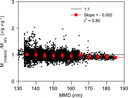
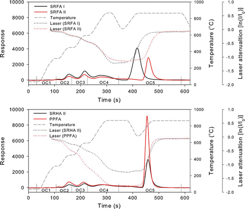
FIG. 13 M COSMOS/M SP2 ratio versus the MMD of BC. The solid black line is the least squares fitted line, and the red squares denote the mean M COSMOS/M SP2 ratios for 10-nm MMD bins.

Reprints and Corporate Permissions

Please note: Selecting permissions does not provide access to the full text of the article, please see our help page How do I view content?

To request a reprint or corporate permissions for this article, please click on the relevant link below:

Academic Permissions

Please note: Selecting permissions does not provide access to the full text of the article, please see our help page How do I view content?

Obtain permissions instantly via Rightslink by clicking on the button below:

If you are unable to obtain permissions via Rightslink, please complete and submit this Permissions form. For more information, please visit our Permissions help page.