2,079
Views
43
CrossRef citations to date
0
Altmetric
Original Articles

Thermophoresis of a Spherical Particle: Reassessment, Clarification, and New Analysis

Pages 927-948 | Received 11 May 2010, Accepted 21 Feb 2011, Published online: 12 Apr 2011

Figures & data

Table 1 Theoretical expressions for the functions Φ and Ψ. The current best estimates of the thermal creep, velocity slip, and temperature jump coefficients are Ktc = 1.10, Cm =1.13(2−α m )/α m , and Ce =2.17(2−α e )/α e

Figure 1 Curves of −Φ/(2π) plotted against log10(Kn) for various Λ using the interpolation formula of CitationTalbot et al. (1980) with αm = αe = 1. All curves asymptote to Epstein's continuum limit as Kn→0.
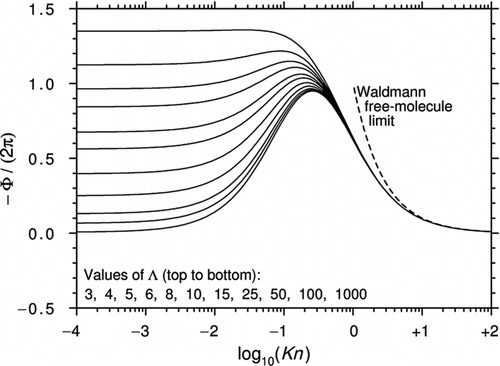
Figure 1 Curves of −Φ/(2π) plotted against log10(Kn) for various Λ using the interpolation formula of CitationTalbot et al. (1980) with αm = αe = 1. All curves asymptote to Epstein's continuum limit as Kn→0.

Figure 2 The spherical polar (r, θ, φ) coordinate system used for the G13 analysis. There is axial symmetry around the z-axis (∂/∂φ=0).
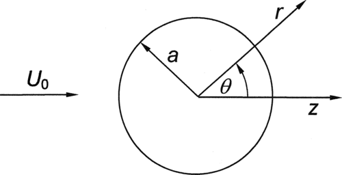
Figure 2 The spherical polar (r, θ, φ) coordinate system used for the G13 analysis. There is axial symmetry around the z-axis (∂/∂φ=0).

Figure 3 Curves of −Φ/(2π) plotted against log10(Kn) for various Λ using Equation (31a) (Brock's theory plus the temperature-driven part of the thermal stress). Reversed thermophoresis at high Λ is evident but the behavior at high Kn is nonphysical.
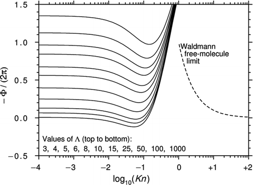
Figure 3 Curves of −Φ/(2π) plotted against log10(Kn) for various Λ using Equation (31a) (Brock's theory plus the temperature-driven part of the thermal stress). Reversed thermophoresis at high Λ is evident but the behavior at high Kn is nonphysical.

Figure 4 Curves of −Φ/(2π) plotted against log10(Kn) for various Λ using Equation (32a) (Dwyer's theory with the pressure-driven heat flux included correctly). For Kn < 0.2, the curves are almost identical to those of but the behavior at high Kn is nonphysical.
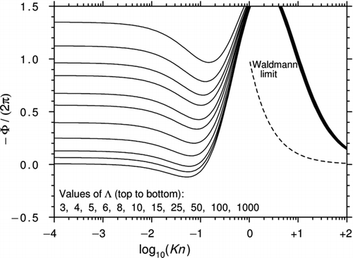
Figure 4 Curves of −Φ/(2π) plotted against log10(Kn) for various Λ using Equation (32a) (Dwyer's theory with the pressure-driven heat flux included correctly). For Kn < 0.2, the curves are almost identical to those of Figure 3 but the behavior at high Kn is nonphysical.

Figure 5 Diagram to illustrate the calculation of the free-molecule distribution function fFM .

Figure 5 Diagram to illustrate the calculation of the free-molecule distribution function fFM .

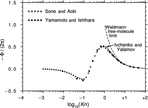
Figure 6 Curves of −Φ/(2π) plotted against log10(Kn) for a perfect thermally conducting sphere (Λ→∞). The calculations are from Sone and Aoki (1981, 1983) and CitationYamamoto and Ishihara (1988). Also shown is Equation (43) from Ivchenko and Yalamov, the first-order correction in

to Waldmann's free-molecule expression.

Figure 6 Curves of −Φ/(2π) plotted against log10(Kn) for a perfect thermally conducting sphere (Λ→∞). The calculations are from Sone and Aoki (1981, 1983) and CitationYamamoto and Ishihara (1988). Also shown is Equation (43) from Ivchenko and Yalamov, the first-order correction in Display full size to Waldmann's free-molecule expression.

Table 2 Published experimental data for the thermophoretic force

Figure 7 Curves of −Φ/(2π) plotted against log10(Kn) for various Λ from CitationYamamoto and Ishihara (1988). The black circles are calculated from Equation (44) and Tables 1 and 2 of the original article. Also shown are the Epstein continuum limits.
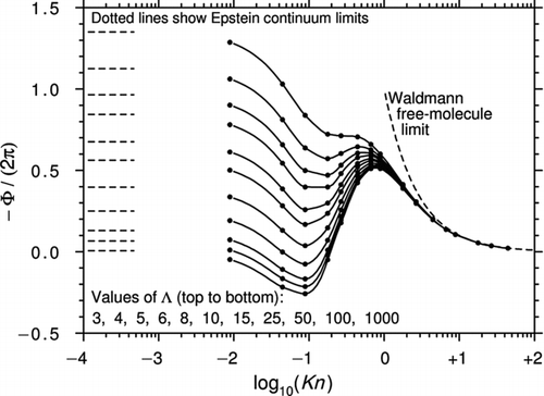
Figure 7 Curves of −Φ/(2π) plotted against log10(Kn) for various Λ from CitationYamamoto and Ishihara (1988). The black circles are calculated from Equation (44) and Tables 1 and 2 of the original article. Also shown are the Epstein continuum limits.

Figure 8 Curves of −Φ/(2π) plotted against log10(Kn) for various Λ from CitationBeresnev and Chernyak (1995). The black circles are calculated from Equation (45) and Table 1 of Beresnev and Chernyak. Also shown are the Epstein continuum limits.
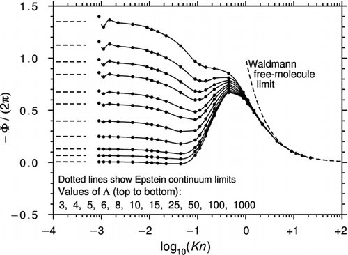
Figure 8 Curves of −Φ/(2π) plotted against log10(Kn) for various Λ from CitationBeresnev and Chernyak (1995). The black circles are calculated from Equation (45) and Table 1 of Beresnev and Chernyak. Also shown are the Epstein continuum limits.

Figure 9 The thermophoretic force data of (a) CitationSchmitt (1959); (b) CitationSchadt and Cadle (1961); (c) CitationJacobsen and Brock (1965); (d), (e), and (f) Li and Davis (1995a, 1995b). Theoretical predictions for the corresponding values of Λ: Beresnev and Chernyak (solid lines), Yamamoto and Ishihara (dotted lines).
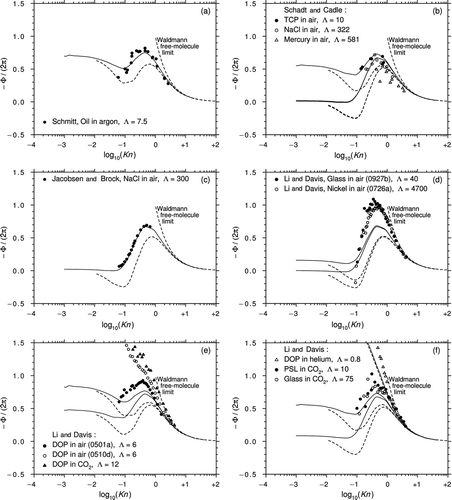
Figure 9 The thermophoretic force data of (a) CitationSchmitt (1959); (b) CitationSchadt and Cadle (1961); (c) CitationJacobsen and Brock (1965); (d), (e), and (f) Li and Davis (1995a, 1995b). Theoretical predictions for the corresponding values of Λ: Beresnev and Chernyak (solid lines), Yamamoto and Ishihara (dotted lines).
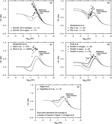
Table 3 Published experimental data for the thermophoretic velocity

Figure 10 The thermophoretic velocity data of (a) CitationSchmitt (1959), (b) and (c) CitationSantachiara et al. (2002), (d) CitationProdi et al. (2007), and (e) CitationSagot et al. (2009). Theoretical predictions for the corresponding values of Λ: Beresnev and Chernyak (solid lines), Yamamoto and Ishihara (dotted lines).

Figure 10 The thermophoretic velocity data of (a) CitationSchmitt (1959), (b) and (c) CitationSantachiara et al. (2002), (d) CitationProdi et al. (2007), and (e) CitationSagot et al. (2009). Theoretical predictions for the corresponding values of Λ: Beresnev and Chernyak (solid lines), Yamamoto and Ishihara (dotted lines).

Figure 11 Curves of −Φ/(2π) plotted against log10(Kn) for various Λ. The white circles are from CitationYamamoto and Ishihara (1988), the black circles are from CitationBeresnev and Chernyak (1995), and the solid lines are from the interpolation formula Equation (47) with Cint = 0.5.
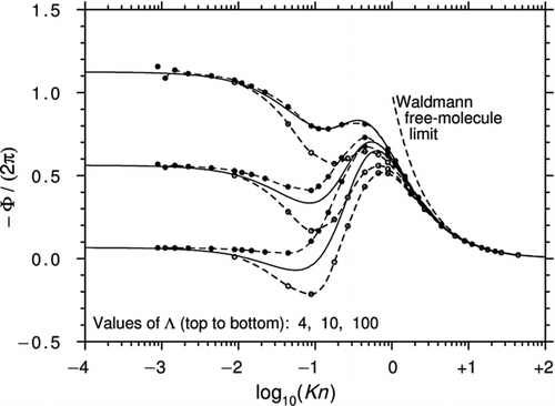
Figure 11 Curves of −Φ/(2π) plotted against log10(Kn) for various Λ. The white circles are from CitationYamamoto and Ishihara (1988), the black circles are from CitationBeresnev and Chernyak (1995), and the solid lines are from the interpolation formula Equation (47) with Cint = 0.5.

Figure 12 Curves of −Φ/(2π) plotted against log10(Kn) for various Λ using the interpolation formula Equation (47) with Cint = 0.5. For Kn < 0.2, the curves are almost identical to those of Figures 3 and 4. For comparison, the CitationTalbot et al. (1980) prescription is also plotted.
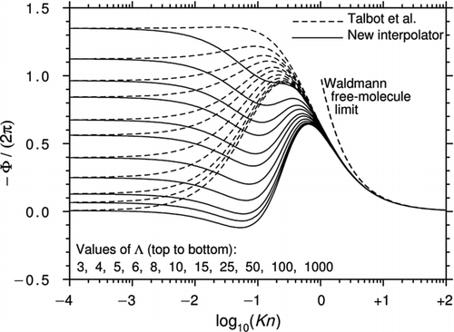
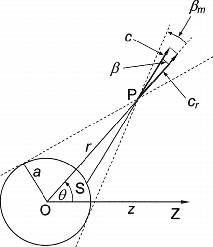
Figure 12 Curves of −Φ/(2π) plotted against log10(Kn) for various Λ using the interpolation formula Equation (47) with Cint = 0.5. For Kn < 0.2, the curves are almost identical to those of Figures 3 and 4. For comparison, the CitationTalbot et al. (1980) prescription is also plotted.

Reprints and Corporate Permissions

Please note: Selecting permissions does not provide access to the full text of the article, please see our help page How do I view content?

To request a reprint or corporate permissions for this article, please click on the relevant link below:

Academic Permissions

Please note: Selecting permissions does not provide access to the full text of the article, please see our help page How do I view content?

Obtain permissions instantly via Rightslink by clicking on the button below:

If you are unable to obtain permissions via Rightslink, please complete and submit this Permissions form. For more information, please visit our Permissions help page.