1,489
Views
48
CrossRef citations to date
0
Altmetric
Original Articles

Interpretation of Secondary Organic Aerosol Formation from Diesel Exhaust Photooxidation in an Environmental Chamber

, , , &
Pages 964-972 | Received 12 Nov 2010, Accepted 10 Mar 2011, Published online: 14 Apr 2011

Figures & data

FIG. 1 A schematic diagram of the College of Engineering-Center for Environmental Research and Technology, University of California, Riverside (CE-CERT/UC) mezzanine chamber.
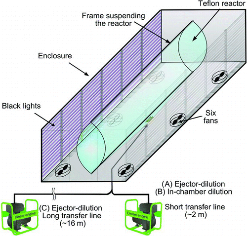
FIG. 1 A schematic diagram of the College of Engineering-Center for Environmental Research and Technology, University of California, Riverside (CE-CERT/UC) mezzanine chamber.

TABLE 1 Engine load, initial concentrations, calculated OH concentration, Df , bulk effective density, and overall dilution ratio

FIG. 2 Time series of (a) particle volume concentration and mass concentration, (b) volume fraction remaining (100°C), (c) effective density, fractal-like dimension (Df ), and (d) OA fraction. See text for detail (Results of Run 1) (conc.: concentration).
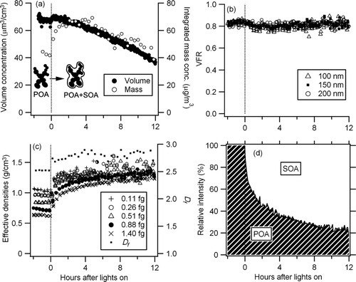
FIG. 2 Time series of (a) particle volume concentration and mass concentration, (b) volume fraction remaining (100°C), (c) effective density, fractal-like dimension (Df ), and (d) OA fraction. See text for detail (Results of Run 1) (conc.: concentration).

FIG. 3 Time series of selected ions measured by an AMS (Run 1).

FIG. 3 Time series of selected ions measured by an AMS (Run 1).

FIG. 4 Aerosol mass spectrums of diesel exhaust particulate before and after UV irradiation (Run 1) (BL: black light).
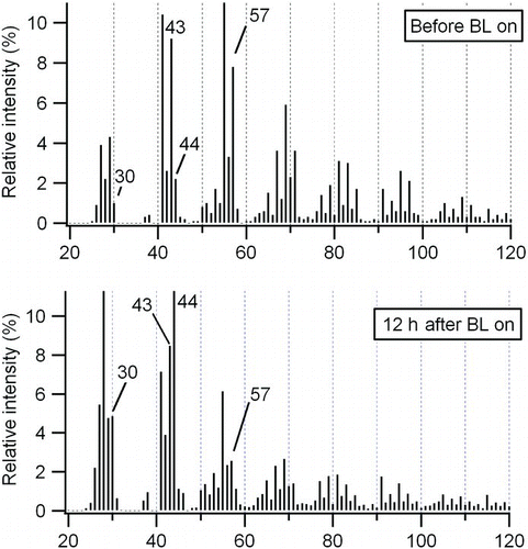
FIG. 4 Aerosol mass spectrums of diesel exhaust particulate before and after UV irradiation (Run 1) (BL: black light).

FIG. 5 Evolution of particle volume, mass concentration, and bulk effective density (*Lights were not turned on for Run 10 but shown for the sake of comparison. Time injection completed is set to −2 h.).
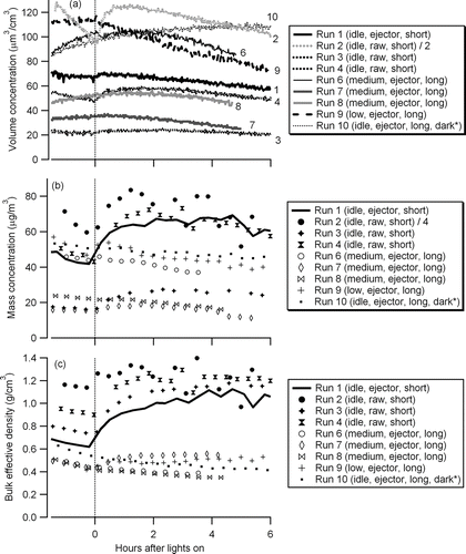
FIG. 5 Evolution of particle volume, mass concentration, and bulk effective density (*Lights were not turned on for Run 10 but shown for the sake of comparison. Time injection completed is set to −2 h.).

FIG. 6 Effective densities of particles in an environmental chamber and dilution ratio when the injection was completed (dil.: dilution).
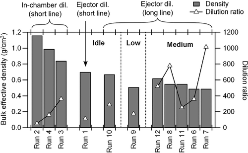
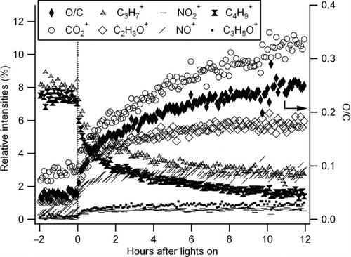
FIG. 6 Effective densities of particles in an environmental chamber and dilution ratio when the injection was completed (dil.: dilution).
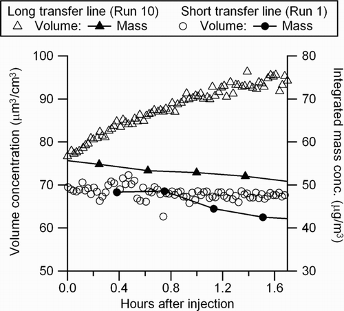
FIG. 7 Time series of particle volume and mass concentration before lights are turned on. Comparison of short transfer line (Run 1) and long transfer line (Run 10) experiments at idle (conc.: concentration).

FIG. 7 Time series of particle volume and mass concentration before lights are turned on. Comparison of short transfer line (Run 1) and long transfer line (Run 10) experiments at idle (conc.: concentration).

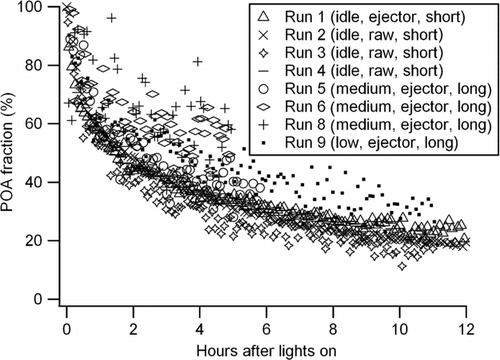
FIG. 8 Evolution of POA fraction calculated by the AMS C4H9 + tracer method (Equation (2), see text).

FIG. 8 Evolution of POA fraction calculated by the AMS C4H9 + tracer method (Equation (2), see text).

Reprints and Corporate Permissions

Please note: Selecting permissions does not provide access to the full text of the article, please see our help page How do I view content?

To request a reprint or corporate permissions for this article, please click on the relevant link below:

Academic Permissions

Please note: Selecting permissions does not provide access to the full text of the article, please see our help page How do I view content?

Obtain permissions instantly via Rightslink by clicking on the button below:

If you are unable to obtain permissions via Rightslink, please complete and submit this Permissions form. For more information, please visit our Permissions help page.