4,465
Views
46
CrossRef citations to date
0
Altmetric
Original Articles

Characterization of Laser Printer Nanoparticle and VOC Emissions, Formation Mechanisms, and Strategies to Reduce Airborne Exposures

, &
Pages 1060-1068 | Received 15 Jul 2010, Accepted 23 Nov 2010, Published online: 10 May 2011

Figures & data

FIG. 1 Sampling locations for VOC and particulate matter sampling. (Figure provided in color online.)
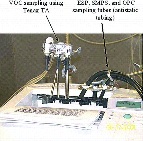
FIG. 1 Sampling locations for VOC and particulate matter sampling. (Figure provided in color online.)

FIG. 2 Typical measured CPC particle number concentration at the paper discharge point versus time for cold (room temperature) start-up, showing a rapidly decaying emission level.
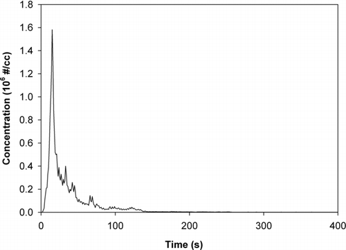
FIG. 2 Typical measured CPC particle number concentration at the paper discharge point versus time for cold (room temperature) start-up, showing a rapidly decaying emission level.

FIG. 3 Normalized size distributions for 7 consecutive sets of 45 page print jobs, demonstrating particle size increases with the number of pages printed, likely due to increasing agglomeration. (Figure provided in color online.)
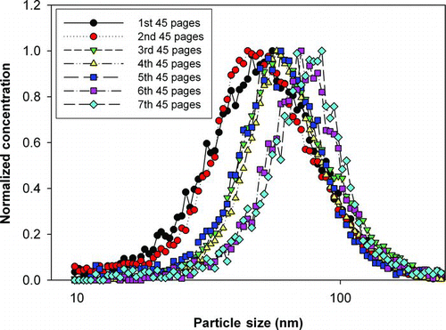
FIG. 3 Normalized size distributions for 7 consecutive sets of 45 page print jobs, demonstrating particle size increases with the number of pages printed, likely due to increasing agglomeration. (Figure provided in color online.)

FIG. 4 5Peak emitted nanoparticle concentrations measured by CPC versus idle time between printings for a 45 page print job, showing that the particle number concentration is less than 50% of the original concentration when the waiting time is less than 60 min.
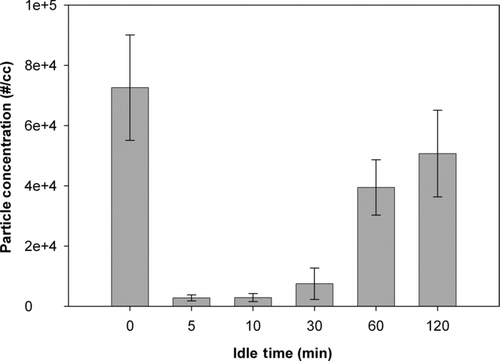
FIG. 4 5Peak emitted nanoparticle concentrations measured by CPC versus idle time between printings for a 45 page print job, showing that the particle number concentration is less than 50% of the original concentration when the waiting time is less than 60 min.

FIG. 5 Nanoparticle emissions produced without printing from fuser heating during repeated printer power up cycles, with and without toner cartridge inserted.
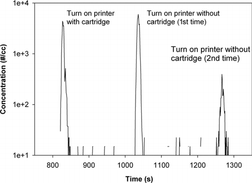
FIG. 5 Nanoparticle emissions produced without printing from fuser heating during repeated printer power up cycles, with and without toner cartridge inserted.

FIG. 6 Number particle size distributions measured by SMPS for printing different numbers of pages from a cold start-up. (Figure provided in color online.)
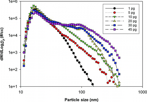
FIG. 6 Number particle size distributions measured by SMPS for printing different numbers of pages from a cold start-up. (Figure provided in color online.)

FIG. 7 (a) 2000× SEM image of toner powder, dominated by 3–8 μm clumps of 25–400 nm agglomerates, each composed of carbon, iron, and oxygen. Also present are 1–3 μm strontium–titanium–oxygen particles (bright particles). (b) 97,000× TEM image of the 25–400 nm agglomerates, each composed of an iron–oxygen core (dark shapes) coated with 5–15 nm carbon–oxygen particles.
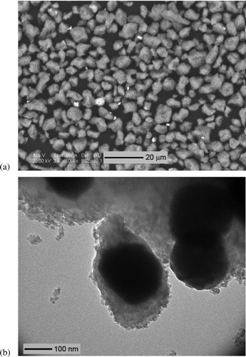
FIG. 7 (a) 2000× SEM image of toner powder, dominated by 3–8 μm clumps of 25–400 nm agglomerates, each composed of carbon, iron, and oxygen. Also present are 1–3 μm strontium–titanium–oxygen particles (bright particles). (b) 97,000× TEM image of the 25–400 nm agglomerates, each composed of an iron–oxygen core (dark shapes) coated with 5–15 nm carbon–oxygen particles.

FIG. 8 SEM image of printed page, showing melted toner in the shape of printed letters and paper coating (nonmelted particles attached to the paper fibers).
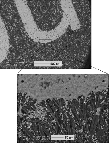
FIG. 8 SEM image of printed page, showing melted toner in the shape of printed letters and paper coating (nonmelted particles attached to the paper fibers).

FIG. 9 TGA analysis of the toner powder showing mass loss as a function of temperature.

FIG. 9 TGA analysis of the toner powder showing mass loss as a function of temperature.

FIG. 10 DSC analysis of toner powder showing the phase change of the copolymer of toner powder.

FIG. 10 DSC analysis of toner powder showing the phase change of the copolymer of toner powder.

FIG. 11 GC/MS results for VOCs emitted from LaserJet printer, for sampling conducted only during printing cycles.
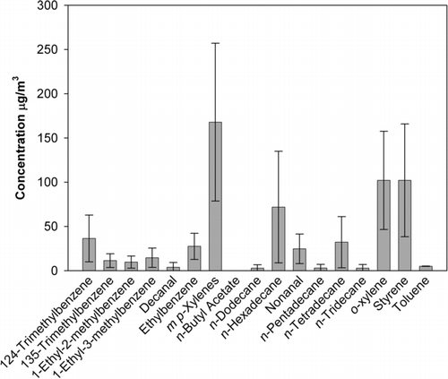
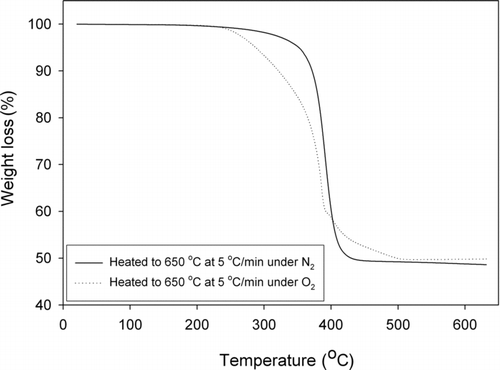
FIG. 11 GC/MS results for VOCs emitted from LaserJet printer, for sampling conducted only during printing cycles.
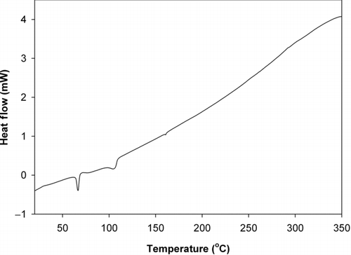
TABLE 1 Maximum VOC emissions, estimated using TGA test results for expected copolymer melting temperature range

Reprints and Corporate Permissions

Please note: Selecting permissions does not provide access to the full text of the article, please see our help page How do I view content?

To request a reprint or corporate permissions for this article, please click on the relevant link below:

Academic Permissions

Please note: Selecting permissions does not provide access to the full text of the article, please see our help page How do I view content?

Obtain permissions instantly via Rightslink by clicking on the button below:

If you are unable to obtain permissions via Rightslink, please complete and submit this Permissions form. For more information, please visit our Permissions help page.