1,419
Views
12
CrossRef citations to date
0
Altmetric
Original Articles

Modeling and Validation of Nanoparticle Charging Efficiency of a Single-Wire Corona Unipolar Charger

, , , &
Pages 1468-1479 | Received 14 Mar 2011, Accepted 14 Jun 2011, Published online: 15 Jul 2011

Figures & data

FIG. 1 Schematic diagram of the present unipolar charger (unit: mm).

FIG. 1 Schematic diagram of the present unipolar charger (unit: mm).

FIG. 2 Schematic diagram of the experimental setup (HEPA, high efficiency particulate air; HV, high voltage).
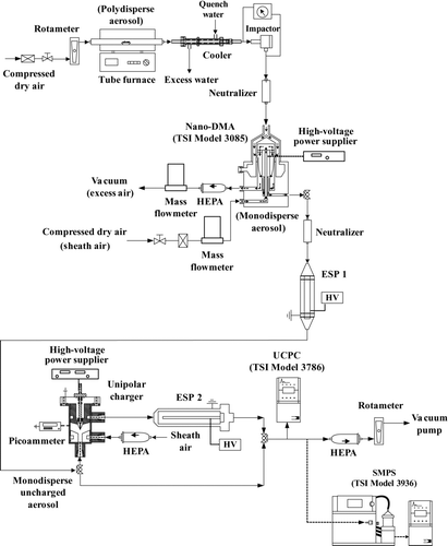
FIG. 2 Schematic diagram of the experimental setup (HEPA, high efficiency particulate air; HV, high voltage).

FIG. 3 Calculation domain in the numerical simulation (unit: mm).

FIG. 3 Calculation domain in the numerical simulation (unit: mm).

FIG. 4 Corona current versus applied voltage.

FIG. 4 Corona current versus applied voltage.

FIG. 5 (a) Experimental extrinsic charging efficiency and (b) electrostatic loss of 20-nm particles versus corona voltage at different sheath airflow rates.
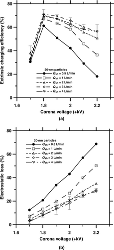
FIG. 5 (a) Experimental extrinsic charging efficiency and (b) electrostatic loss of 20-nm particles versus corona voltage at different sheath airflow rates.

FIG. 6 Comparison of the extrinsic charging efficiencies of the present charger with those of previous corona-based chargers.
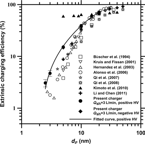
FIG. 6 Comparison of the extrinsic charging efficiencies of the present charger with those of previous corona-based chargers.

FIG. 7 (a) Flow streamlines, (b) electric potential field, (c) electric potential field near the discharge wire, and (d) ion concentration field at Q sh = 3 L/min in the present charger. The applied voltage is −2.1 kV. (Color figure available online.)
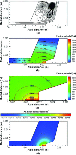
FIG. 7 (a) Flow streamlines, (b) electric potential field, (c) electric potential field near the discharge wire, and (d) ion concentration field at Q sh = 3 L/min in the present charger. The applied voltage is −2.1 kV. (Color figure available online.)

FIG. 8 Number concentration field of 20 nm particles carrying 0–2 charges in the present charger when the applied voltage was −2.1 kV at Q sh = 3 L/min. (a) 0 charge, (b) 1 charge, (c) 2 charges. (Color figure available online.)
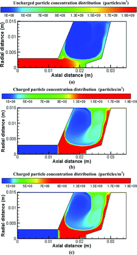
FIG. 8 Number concentration field of 20 nm particles carrying 0–2 charges in the present charger when the applied voltage was −2.1 kV at Q sh = 3 L/min. (a) 0 charge, (b) 1 charge, (c) 2 charges. (Color figure available online.)

FIG. 9 Comparison of the extrinsic charging efficiency of the present charger between the numerical results and experimental data at Q sh = 3 L/min. (a) Positive voltage, (b) negative voltage.
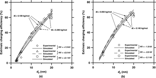
FIG. 9 Comparison of the extrinsic charging efficiency of the present charger between the numerical results and experimental data at Q sh = 3 L/min. (a) Positive voltage, (b) negative voltage.
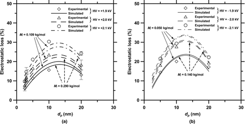
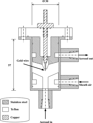
FIG. 10 Comparison of the electrostatic loss of the present charger between the numerical results and experimental data at Q sh = 3 L/min. (a) Positive voltage, (b) negative voltage.
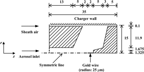
FIG. 10 Comparison of the electrostatic loss of the present charger between the numerical results and experimental data at Q sh = 3 L/min. (a) Positive voltage, (b) negative voltage.
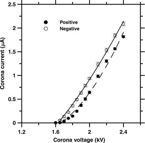
FIG. 11 Comparison of the intrinsic charging efficiency of the present charger between the numerical results and experimental data at Q sh = 3 L/min. (a) Positive voltage, (b) negative voltage.
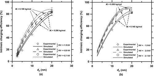
FIG. 11 Comparison of the intrinsic charging efficiency of the present charger between the numerical results and experimental data at Q sh = 3 L/min. (a) Positive voltage, (b) negative voltage.
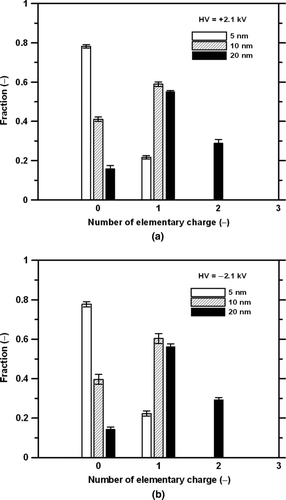
FIG. 12 Measured charge distribution at the exit of the present charger at Q sh = 3 L/min at the applied voltage of (a) +2.1 kV and (b) −2.1 kV.

FIG. 12 Measured charge distribution at the exit of the present charger at Q sh = 3 L/min at the applied voltage of (a) +2.1 kV and (b) −2.1 kV.
Supplemental material

uast_a_600785_sup_20016771.zip

Download Zip (57.5 KB)

Reprints and Corporate Permissions

Please note: Selecting permissions does not provide access to the full text of the article, please see our help page How do I view content?

To request a reprint or corporate permissions for this article, please click on the relevant link below:

Academic Permissions

Please note: Selecting permissions does not provide access to the full text of the article, please see our help page How do I view content?

Obtain permissions instantly via Rightslink by clicking on the button below:

If you are unable to obtain permissions via Rightslink, please complete and submit this Permissions form. For more information, please visit our Permissions help page.