Figures & data
FIG. 1 (a) Photo and (b) diagram illustrating components and measurements of the nanomaterial aerosol generation system. (Color figure available online.)
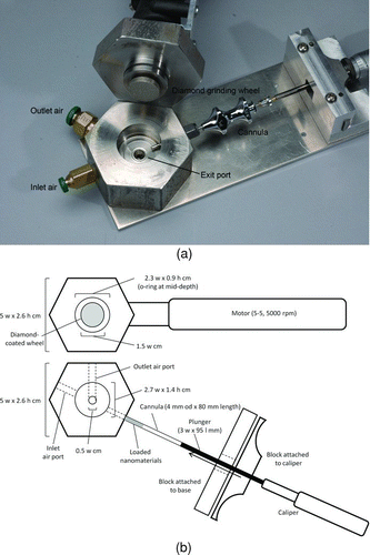
FIG. 2 Diagram of aerosolization and nose-only inhalation system.
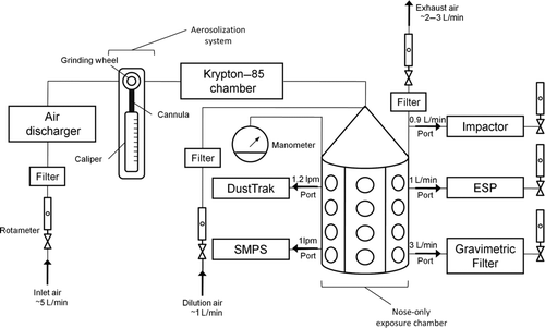
FIG. 3 Real-time DustTrak reading during aerosolization of FeSW-CNT at ∼1000 μg/m3.
TABLE 1 Summary of bulk and aerosolized carbon nanomaterial characteristics
FIG. 4 TEM micrographs of aerosolized (a) FeSW-CNTs and (b) cSW-CNTs.
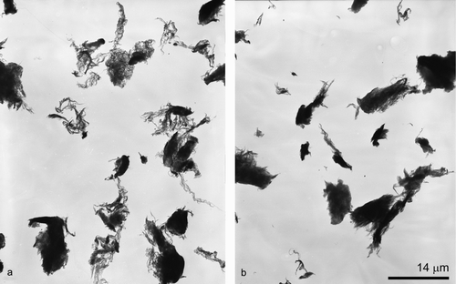
FIG. 5 TEM micrographs of aerosolized (a) FeSW-CNTs and (b) cSW-CNTs illustrating the morphology and presence or absence of residual iron catalyst nanoparticles.
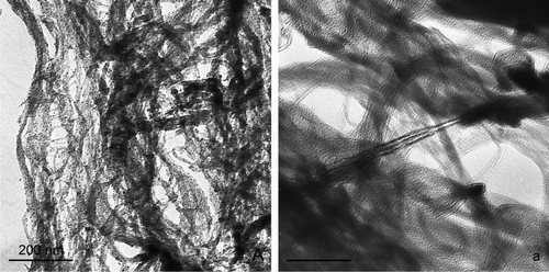
FIG. 6 TEM micrographs illustrating the morphology and substructures of some of the smallest aerosolized particles of (a, b) carbon black, (c, d) FeSW-CNTs, and (e, f) cSW-CNTs. At the smallest dimensions, these particles existed in an agglomerated state. (a, b) Carbon black appeared as an agglomerated chain of smaller irregularly shaped spheres, (c, d) FeSW-CNTs existed as a loose tangled “bird's nest” mat of individual and bundled CNTs, while (e) cSW-CNTs appeared as smooth, blocky, torn sheets with individual and bundled CNTs only visualized at the very edges of the agglomerated particles (shown in arrows in f).
TABLE 2 Raman band frequency for aerosolized SW-CNTs and carbon black
FIG. 7 Raman spectra of aerosolized carbon nanomaterials. Spectra profile represents the relative and not the absolute intensity of the Raman peak measurements of the different samples to interpret the structural composition.
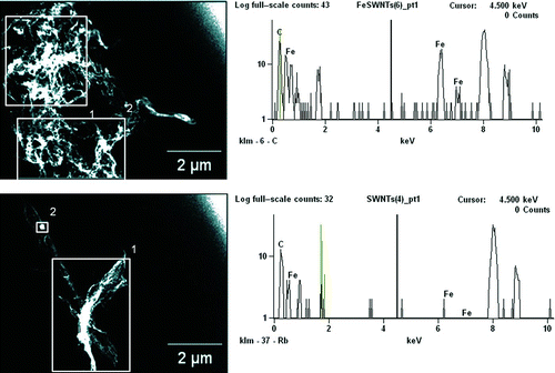
FIG. 8 TEM micrographs and EDS spectra of aerosolized (a) FeSW-CNTs and (b) cSW-CNTs illustrating the morphology and presence or absence of residual iron catalyst nanoparticles. Squares in the images represent the area over which the EDS spectra were analyzed for the elemental composition of aerosolized nanomaterials. The elemental profile as shown in the EDS spectra on the right represents the area analyzed in square 1 of the TEM images shown on the left. (Color figure available online.)