Figures & data
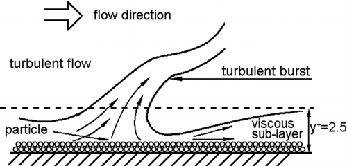
FIG. 1 Schematic diagram of a turbulent burst near the wall (Cleaver and Yates Citation1973).
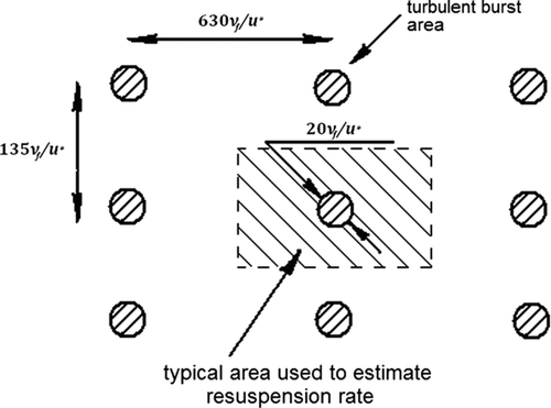
Schematic diagram of turbulent burst distribution on the surface (Cleaver and Yates Citation1973).
Forces acting on a small aggregate in a viscous sublayer (Theerachaisupakjj et al. 2003).
FIG. 4 Critical jump-start air velocity versus particle diameter (with parameters in ).
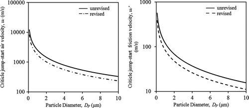
TABLE 1 Condition/parameters for critical jump-start air velocity calculation shown in Figure 4
FIG. 5 Calculated α (with parameters in ).
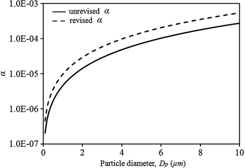
FIG. 6 Particle resuspension rate at time t = 100 s versus particle diameter.
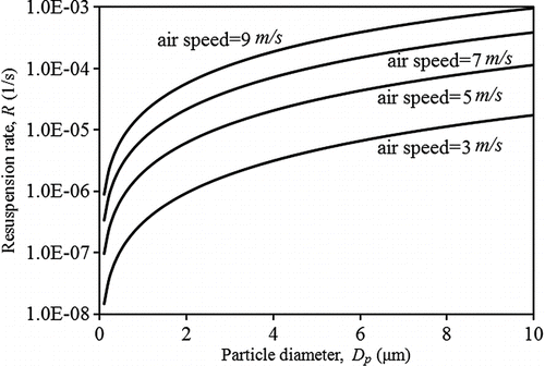
FIG. 7 Particle resuspension rate at time t = 100 s versus average air speed in ducts.
FIG. 8 Particle resuspension rate of particle with diameter of 1 μm versus time.
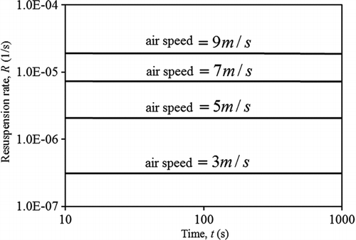
TABLE 2 Parameters of Nicholson's experiment
FIG. 9 Comparison with the experimental data of Nicholson: Resuspension rate from a grass surface vs. particle diameter at time = 50 s.
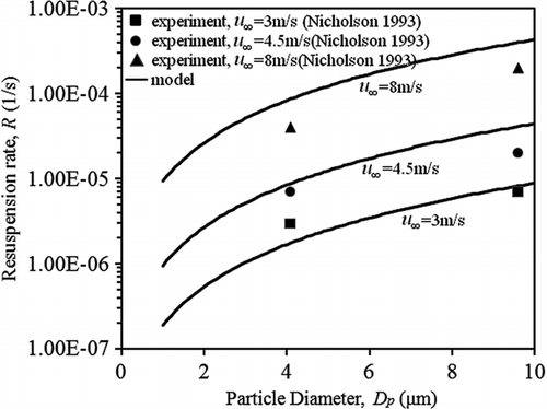
FIG. 10 Comparison with the experimental data of Nicholson: Resuspension rate from a grass surface vs. air speed at time = 50 s.
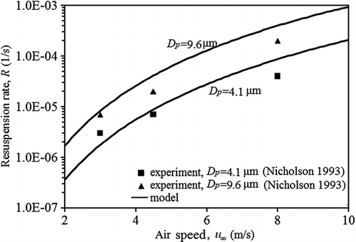
FIG. 11 Comparison with the experimental data of Nicholson: resuspension rate versus time.
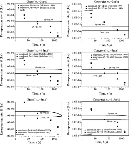
TABLE 3 Parameters of Giess et al.'s experiment
FIG. 12 Comparison with the experimental data of Giess and others: resuspension rate versus air speed on short grass surfaces.
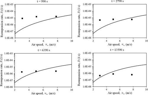
TABLE 4 Parameters for model calculation of Lengweiler's experimental case
FIG. 13 Comparison with the experiment of Lengweiler: resuspension rate versus u ∞, comparison of model and experiment.
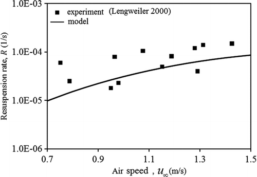
FIG. 14 Particle resuspension rate with revised K versus time with C′ = 0.01.
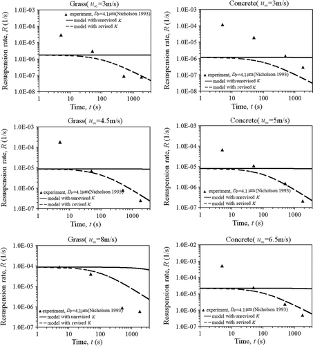
TABLE 5 Model sensitivity analysis results
FIG. 15 Particle resuspension rate with revised K versus diameter with C′ = 0.01.
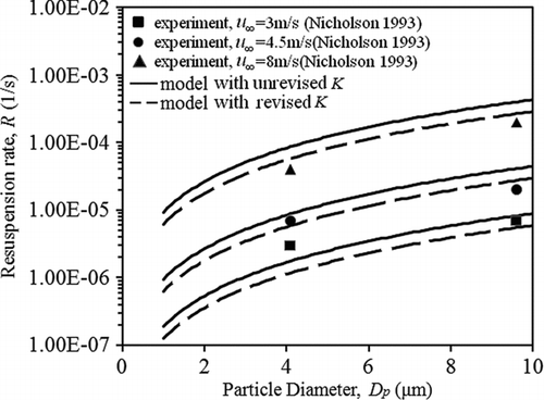
FIG. 16 Particle resuspension rate with revised K versus air speed with C′ = 0.01.
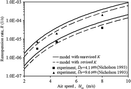
FIG. 17 Resuspension rate R versus the revised rate constant K (air speed u ∞ is 5 m/s, particle diameter Dp is 5 μm, and time is from 0 to 3600 s).
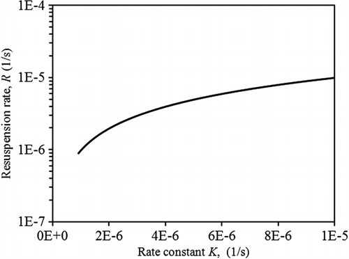
FIG. 18 Resuspension rate R versus particle load N(Dp ) at time t = 100 s (Since t is fixed, K remains constant), when air speed u ∞ is 5 m/s, particle diameter Dp ranges from 0.1 to 10 μm, the initial particle number load N 0 is set to be 8×10¹⁰ per m2.
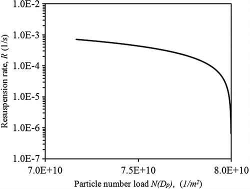
TABLE 6 Resuspension rate change with unit change of input parameters at typical value
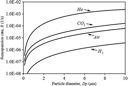
FIG. 19 Particle resuspension rate with different working fluids (Helium, Carbon Dioxide, Air, and Hydrogen).