Figures & data
FIG. 1 Experimental setup: APS, Aerodynamic Particle Sizer; FMPS, Fast Mobility Particle Sizer; SMPS, Scanning Mobility Particle Sizer. For PM collection, 37-mm Teflon, 47-mm Teflon, and quartz filters were used. Total inflow for all the three concentrators were 5000 L/min, and outflows for coarse, fine, and ultrafine concentrators were 52, 56, and 66 L/min, respectively.
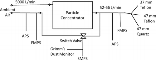
FIG. 2 Size distribution with respect to averaged particle number concentration (N), surface area (S), and volume (V) of (a) ambient particulate matter (APM) and (b) concentrated ambient particulates (CAP), during characterization of the coarse concentrator on different days [D1 (Feb 19) and D2 (Feb 22)]. Y- and X-axes are on log scale. (Color figure available online.)
![FIG. 2 Size distribution with respect to averaged particle number concentration (N), surface area (S), and volume (V) of (a) ambient particulate matter (APM) and (b) concentrated ambient particulates (CAP), during characterization of the coarse concentrator on different days [D1 (Feb 19) and D2 (Feb 22)]. Y- and X-axes are on log scale. (Color figure available online.)](/cms/asset/827c34b5-0022-4bb8-9ab1-9cbd8234c3e6/uast_a_686674_o_f0002g.jpg)
FIG. 3 Size distribution with respect to averaged particle number concentration (N), surface area (S), and volume (V) of (a) ambient particulate matter (APM) and (b) concentrated ambient particulates (CAP), during characterization of the fine concentrator on different days [D1 (Feb 23), D2 (Feb 24), and D3 (Feb 25)]. X-axis is on log scale. (Color figure available online.)
![FIG. 3 Size distribution with respect to averaged particle number concentration (N), surface area (S), and volume (V) of (a) ambient particulate matter (APM) and (b) concentrated ambient particulates (CAP), during characterization of the fine concentrator on different days [D1 (Feb 23), D2 (Feb 24), and D3 (Feb 25)]. X-axis is on log scale. (Color figure available online.)](/cms/asset/50f1db0c-3417-41dd-880c-f4e947b7578c/uast_a_686674_o_f0003g.jpg)
FIG. 4 Size distribution with respect to averaged particle number concentration (N), surface area (S), and volume (V) of (a) ambient particulate matter (APM) and (b) concentrated ambient particulates (CAP), based on FMPS data during characterization of the ultrafine concentrator on March 3. X-axis is on log scale. (Color figure available online.)
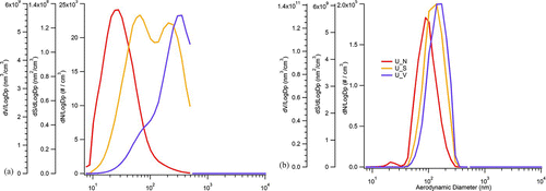
FIG. 5 Number-concentration-based size distribution of concentrated and ambient particulate matter with the ultrafine concentrator during the last week of the campaign. Note: CAP, concentrated ambient particulate; APM, ambient particulate matter. (Color figure available online.)
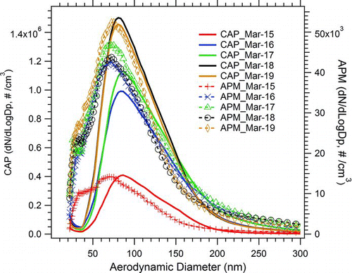
FIG. 6 Number-concentration-based size distribution of concentrated (left axis) and nonconcentrated (right axis) known particles, and their ratio for each size bin while testing the ultrafine concentrator.
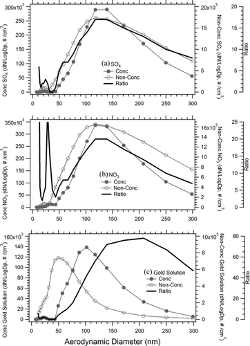
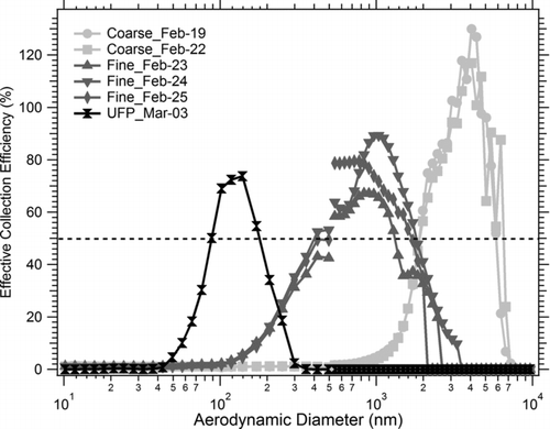
FIG. 7 Effective collection efficiencies as a function of particle size for all three concentrators on each of the characterization days. X-axis is on log scale.
