987
Views
2
CrossRef citations to date
0
Altmetric
Regular Articles

Night-Time Ground Hyperspectral Imaging for Urban-Scale Remote Sensing of Ambient PM. I. Aerosol Optical Thickness Acquisition

, , , &
Pages 1119-1128 | Received 15 Nov 2011, Accepted 21 Apr 2012, Published online: 27 Jun 2012

Figures & data

FIG. 1 Side view (top) and top view (bottom) of the laboratory setup for spectral imaging and radiometric measurements (dimensions in cm). A: the HS sensor (either the HS camera or the spectroradiometer); B: a transparent aerosol chamber; C: halogen source; and D: a reflecting standard.
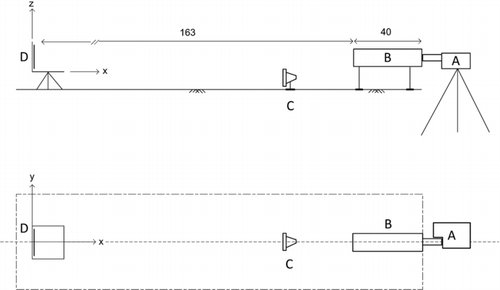
FIG. 1 Side view (top) and top view (bottom) of the laboratory setup for spectral imaging and radiometric measurements (dimensions in cm). A: the HS sensor (either the HS camera or the spectroradiometer); B: a transparent aerosol chamber; C: halogen source; and D: a reflecting standard.

FIG. 2 Aerial photographs of the field experiments. (a) The short (180 m) open path stretched between the sensor location (A) and the target location (B) along the Zin valley. (b) The long (4.4 km) open path stretched between the sensor at the Ben-Gurion Heritage Institute (C) and the target location near the Tsiporim junction (D). (Color figure available online.)
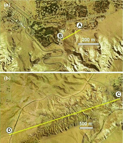
FIG. 2 Aerial photographs of the field experiments. (a) The short (180 m) open path stretched between the sensor location (A) and the target location (B) along the Zin valley. (b) The long (4.4 km) open path stretched between the sensor at the Ben-Gurion Heritage Institute (C) and the target location near the Tsiporim junction (D). (Color figure available online.)

FIG. 3 Radiometric calibration coefficients derived from the least squares regression (average ± standard deviation). Top: the slope b 1(λ); bottom: the intercept b 0(λ). (Color figure available online.)
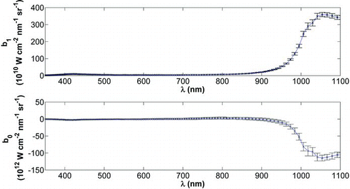
FIG. 3 Radiometric calibration coefficients derived from the least squares regression (average ± standard deviation). Top: the slope b 1(λ); bottom: the intercept b 0(λ). (Color figure available online.)

FIG. 4 Nominal error of the acquired aerosol spectral optical thickness, Δτ a , due to the radiometric calibration errors.
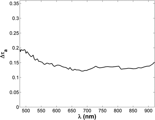
FIG. 4 Nominal error of the acquired aerosol spectral optical thickness, Δτ a , due to the radiometric calibration errors.

FIG. 5 (a) Night-time and (b) daytime scenery of the short (180 m) open path field imaging at the Ben-Gurion Heritage Institute. The center of the halogen source (black core) is marked by a cross in the night-time scene. The four peripheral registration spotlights are arranged in a quadrilateral shape around it. (Color figure available online.)
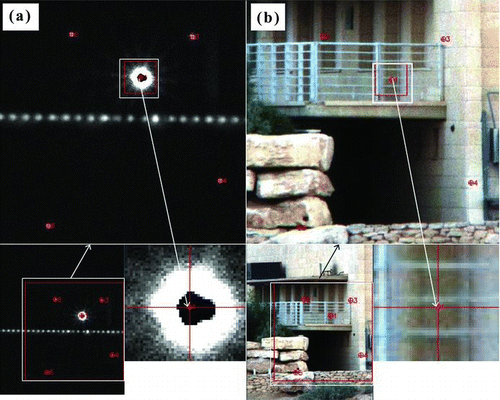
FIG. 5 (a) Night-time and (b) daytime scenery of the short (180 m) open path field imaging at the Ben-Gurion Heritage Institute. The center of the halogen source (black core) is marked by a cross in the night-time scene. The four peripheral registration spotlights are arranged in a quadrilateral shape around it. (Color figure available online.)

FIG. 6 Classification of pixels for analysis (ring arrangement). (a) Selected pixels after the k-means classification step (k=10, 5% threshold, 5 iterations, 313 pixels). (b) Sub-selection of pixels with high intensity by the kNN procedure (k=8, SD=1, 231 pixels). (c) Final selection of the subset of pixels used for analysis after outliers removal (106 pixels). (Color figure available online.)

FIG. 6 Classification of pixels for analysis (ring arrangement). (a) Selected pixels after the k-means classification step (k=10, 5% threshold, 5 iterations, 313 pixels). (b) Sub-selection of pixels with high intensity by the kNN procedure (k=8, SD=1, 231 pixels). (c) Final selection of the subset of pixels used for analysis after outliers removal (106 pixels). (Color figure available online.)

FIG. 7 Time-average (black line) ± one standard deviation (gray lines) of the halogen emission spectra during the short (180 m) open path field imaging in Sede Boker, the Negev desert, on 20 May, 2009. For comparison, a representative halogen reflectance spectrum from the calibration experiment is also shown (gray dotted line).
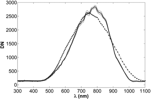
FIG. 7 Time-average (black line) ± one standard deviation (gray lines) of the halogen emission spectra during the short (180 m) open path field imaging in Sede Boker, the Negev desert, on 20 May, 2009. For comparison, a representative halogen reflectance spectrum from the calibration experiment is also shown (gray dotted line).

FIG. 8 Average (dark solid line) and minimal and maximal (light line) size-resolved PM concentrations measured by an aerosol spectrometer during the short (180 m) open path field imaging in Sede-Boker on 20 May, 2009.
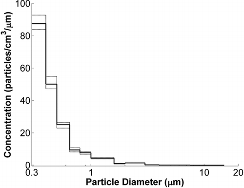
FIG. 8 Average (dark solid line) and minimal and maximal (light line) size-resolved PM concentrations measured by an aerosol spectrometer during the short (180 m) open path field imaging in Sede-Boker on 20 May, 2009.

TABLE 1 Meteorological and PM data recorded between 19:00 and 19:30 at the Neve Shaanan air quality monitoring station, Haifa, during the three 2010 selected events (3 May, 20 June, and 18 August). The station is located in close proximity to the open path through which the HS imaging was performed

FIG. 9 Time-series imaging of the halogen emission through the long (4.4 km) open path in Sede Boker on the evening of 21 May, 2009. Inset: pixels with a relatively high emission used for analysis; 1: pixels with a heterogeneous signature; 2: pixels with a homogeneous signature. Averaged signals of pixels from both classes at 20:10 (black solid line), 20:30 (dark gray line), and 20:50 (light gray line). (Color figure available online.)
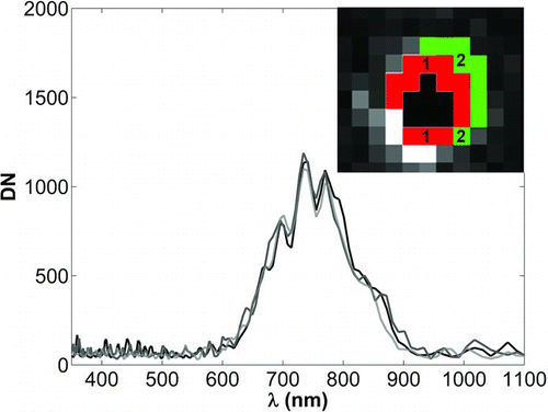
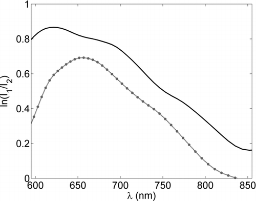
FIG. 9 Time-series imaging of the halogen emission through the long (4.4 km) open path in Sede Boker on the evening of 21 May, 2009. Inset: pixels with a relatively high emission used for analysis; 1: pixels with a heterogeneous signature; 2: pixels with a homogeneous signature. Averaged signals of pixels from both classes at 20:10 (black solid line), 20:30 (dark gray line), and 20:50 (light gray line). (Color figure available online.)

FIG. 10 Attenuation of the halogen emission (I 2) through a 1 km open path in Haifa on the evening of 20 June, 2010 (gray line) and on the evening of 18 August, 2010 (black line) relative to halogen emission on 3 May, 2010 (I 1).

FIG. 10 Attenuation of the halogen emission (I 2) through a 1 km open path in Haifa on the evening of 20 June, 2010 (gray line) and on the evening of 18 August, 2010 (black line) relative to halogen emission on 3 May, 2010 (I 1).

Reprints and Corporate Permissions

Please note: Selecting permissions does not provide access to the full text of the article, please see our help page How do I view content?

To request a reprint or corporate permissions for this article, please click on the relevant link below:

Academic Permissions

Please note: Selecting permissions does not provide access to the full text of the article, please see our help page How do I view content?

Obtain permissions instantly via Rightslink by clicking on the button below:

If you are unable to obtain permissions via Rightslink, please complete and submit this Permissions form. For more information, please visit our Permissions help page.