2,304
Views
42
CrossRef citations to date
0
Altmetric
Regular Articles

Determination of Volatility Distributions of Primary Organic Aerosol Emissions from Internal Combustion Engines Using Thermal Desorption Gas Chromatography Mass Spectrometry

, , &
Pages 1129-1139 | Received 06 Feb 2012, Accepted 17 May 2012, Published online: 27 Jun 2012

Figures & data

FIG. 1 Schematic of experimental setup. Hot, undiluted emissions are sampled into a heated transfer line (150°C) and split into two flows. One portion of the flow is sent to a dilution tunnel for collecting filter and sorbent samples. The other portion of the exhaust is sent through an ejector dilutor and into a smog chamber to measure equilibrium POA partitioning.
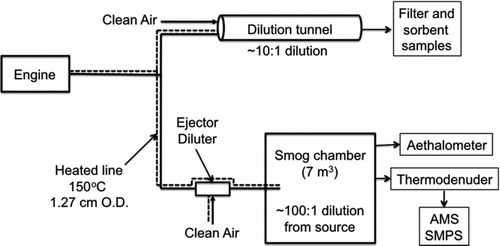
FIG. 1 Schematic of experimental setup. Hot, undiluted emissions are sampled into a heated transfer line (150°C) and split into two flows. One portion of the flow is sent to a dilution tunnel for collecting filter and sorbent samples. The other portion of the exhaust is sent through an ejector dilutor and into a smog chamber to measure equilibrium POA partitioning.

FIG. 2 In-chamber equilibrium partitioning data from a diesel generator experiment. Panel (a) shows the time series of measured CO2 concentration, suspended organic aerosol concentration, and wall-loss corrected COA. Panel (b) is a partitioning plot of the data from panel (a). It shows POA emission factor (EFPOA) as a function of COA. The thick black line shows the predicted EFPOA from the OC/EC and TD-GC-MS analysis of a quartz filter samples (Table S3). The dashed black line shows the predicted EFPOA when IVOC emissions captured by a Tenax sorbent bed placed downstream of the quartz filter are included in the partitioning calculation.
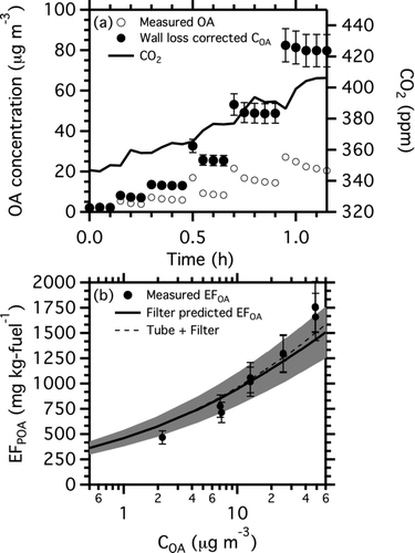
FIG. 2 In-chamber equilibrium partitioning data from a diesel generator experiment. Panel (a) shows the time series of measured CO2 concentration, suspended organic aerosol concentration, and wall-loss corrected COA. Panel (b) is a partitioning plot of the data from panel (a). It shows POA emission factor (EFPOA) as a function of COA. The thick black line shows the predicted EFPOA from the OC/EC and TD-GC-MS analysis of a quartz filter samples (Table S3). The dashed black line shows the predicted EFPOA when IVOC emissions captured by a Tenax sorbent bed placed downstream of the quartz filter are included in the partitioning calculation.

FIG. 3 Partitioning plots for (a) T63 engine, Fischer Tropsch (FT) fuel at idle load; (b) T63 engine, blended fuel at idle load; (c) T63 engine, JP8 fuel, Idle load; and (d) CFM56 engine, JP8 fuel, 4% load. The large point in the upper right of each panel is the artifact-corrected (quartz minus quartz behind Teflon filter) POA emission factor measured with filter samples from a dilution tunnel. The horizontal black dashed line shows the nonvolatile POA assumption. The small points indicate in-chamber partitioning data. Filled points in all panels are from SMPS data corrected for interference from BC. Crosses in panel (c) are AMS data. The multiple shapes (diamonds and triangles) in panel (d) indicate separate experiments. The thick black line is the predicted EFPOA from TD-GC-MS analysis of quartz filter samples. The shaded region shows the range of EFPOA predictions for the mean volatility distributions and the range of EFTOT in Table S3. The thin black lines show the predicted EFPOA when the 20% undesorbed mass is placed into a nonvolatile bin, as described in the text. The OA:BC ratios measured in the dilution tunnel for each of the panels were (a) 30.5, (b) 7.8, (c) 5.1, and (d) 8.2. OA:BC ratios were about a factor of two lower in the chamber than in the dilution tunnel because of differences in OA partitioning.
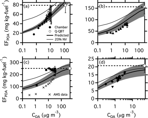
FIG. 3 Partitioning plots for (a) T63 engine, Fischer Tropsch (FT) fuel at idle load; (b) T63 engine, blended fuel at idle load; (c) T63 engine, JP8 fuel, Idle load; and (d) CFM56 engine, JP8 fuel, 4% load. The large point in the upper right of each panel is the artifact-corrected (quartz minus quartz behind Teflon filter) POA emission factor measured with filter samples from a dilution tunnel. The horizontal black dashed line shows the nonvolatile POA assumption. The small points indicate in-chamber partitioning data. Filled points in all panels are from SMPS data corrected for interference from BC. Crosses in panel (c) are AMS data. The multiple shapes (diamonds and triangles) in panel (d) indicate separate experiments. The thick black line is the predicted EFPOA from TD-GC-MS analysis of quartz filter samples. The shaded region shows the range of EFPOA predictions for the mean volatility distributions and the range of EFTOT in Table S3. The thin black lines show the predicted EFPOA when the 20% undesorbed mass is placed into a nonvolatile bin, as described in the text. The OA:BC ratios measured in the dilution tunnel for each of the panels were (a) 30.5, (b) 7.8, (c) 5.1, and (d) 8.2. OA:BC ratios were about a factor of two lower in the chamber than in the dilution tunnel because of differences in OA partitioning.

FIG. 4 Thermograms, plots of POA mass fraction remaining (MFR) as a function of thermodenuder temperature, for the gas-turbine experiments shown in . The symbols are measured MFR from the smog chamber. Black lines are predicted MFR using the volatility distributions listed in Table S3. The grey lines in panels (a–c) show the modeled MFR for particles composed entirely of the lubricating oil used in the T63 engine. The dashed black line in panel (c) shows the effect of assuming that the undesorbed material is nonvolatile, as discussed in the text.
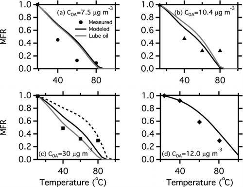
FIG. 4 Thermograms, plots of POA mass fraction remaining (MFR) as a function of thermodenuder temperature, for the gas-turbine experiments shown in Figure 3. The symbols are measured MFR from the smog chamber. Black lines are predicted MFR using the volatility distributions listed in Table S3. The grey lines in panels (a–c) show the modeled MFR for particles composed entirely of the lubricating oil used in the T63 engine. The dashed black line in panel (c) shows the effect of assuming that the undesorbed material is nonvolatile, as discussed in the text.

FIG. 5 (a) C* as a function of GC residence time for a number normal, branched, and cyclic alkanes, naphthalane and substituted naphthalenes, hopanes, oxygenated aromatics, and acids. Vertical dashed lines denote the boundaries of C* bins. Numbers at the top of the bins indicate log(C*) for each bin. More volatile components (higher C*) have shorter retention times. (b) M/z 57 chromatograph of a filter sample collected from the T63 engine operating on JP8 fuel at idle load. (c) Volatility distribution, presented as fi (left axis) and emission factor (right axis) derived from data shown in panel (b). EFTOT, the total emission rate of low-volatility organic material, is the sum of the bars. Error bars show the standard deviation obtained from the analysis of multiple samples with the same engine and load conditions.
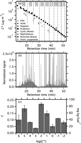
FIG. 5 (a) C* as a function of GC residence time for a number normal, branched, and cyclic alkanes, naphthalane and substituted naphthalenes, hopanes, oxygenated aromatics, and acids. Vertical dashed lines denote the boundaries of C* bins. Numbers at the top of the bins indicate log(C*) for each bin. More volatile components (higher C*) have shorter retention times. (b) M/z 57 chromatograph of a filter sample collected from the T63 engine operating on JP8 fuel at idle load. (c) Volatility distribution, presented as fi (left axis) and emission factor (right axis) derived from data shown in panel (b). EFTOT, the total emission rate of low-volatility organic material, is the sum of the bars. Error bars show the standard deviation obtained from the analysis of multiple samples with the same engine and load conditions.
Supplemental material

uast_a_700430_sup_26724053.zip

Download Zip (239 KB)

Reprints and Corporate Permissions

Please note: Selecting permissions does not provide access to the full text of the article, please see our help page How do I view content?

To request a reprint or corporate permissions for this article, please click on the relevant link below:

Academic Permissions

Please note: Selecting permissions does not provide access to the full text of the article, please see our help page How do I view content?

Obtain permissions instantly via Rightslink by clicking on the button below:

If you are unable to obtain permissions via Rightslink, please complete and submit this Permissions form. For more information, please visit our Permissions help page.