961
Views
20
CrossRef citations to date
0
Altmetric
Regular Articles

Behavior of Alkali Metal Aerosol in a High-Temperature Porous Tube Sampling Probe

, &
Pages 1151-1162 | Received 12 Jan 2012, Accepted 10 May 2012, Published online: 02 Jul 2012

Figures & data

FIG. 1 The experimental setup.

FIG. 1 The experimental setup.

FIG. 2 Scheme of supply system for (a) aerosol precursors, (b) seed particle generation, and (c) aerosol sampling.
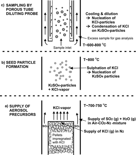
FIG. 2 Scheme of supply system for (a) aerosol precursors, (b) seed particle generation, and (c) aerosol sampling.

TABLE 1 Reactor and sampling conditions, particle concentrations, and particle size modes

FIG. 3 TEM micrograph of K2SO4 particles from conditions corresponding to case 12 in .

FIG. 3 TEM micrograph of K2SO4 particles from conditions corresponding to case 12 in Table 1.

FIG. 4 Measured temperature and mixing profiles of sample in the diluter with a DR of 20 and sampling position B. The values represent conditions in the radial centerline of the tube.
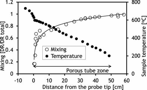
FIG. 4 Measured temperature and mixing profiles of sample in the diluter with a DR of 20 and sampling position B. The values represent conditions in the radial centerline of the tube.

FIG. 5 Sample temperature profiles in the sampling system with two measured and two fictive cases. The values represent conditions in the radial centerline of the tube.
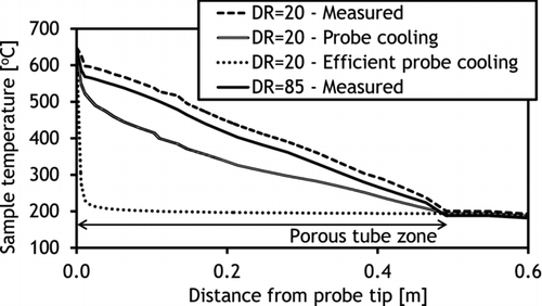
FIG. 5 Sample temperature profiles in the sampling system with two measured and two fictive cases. The values represent conditions in the radial centerline of the tube.

FIG. 6 Sample cooling rates in the diluter given as cumulative distribution (i.e., each value is the average cooling rate from the sample inlet to the corresponding point).
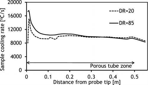
FIG. 6 Sample cooling rates in the diluter given as cumulative distribution (i.e., each value is the average cooling rate from the sample inlet to the corresponding point).

FIG. 7 Particle size distributions with (a) various K2SO4/KCl ratios, (b) various primary DRs, (c) various sampling locations, and (d) comparison of simulated and measured particle size distributions. The number concentrations are dilution-corrected.
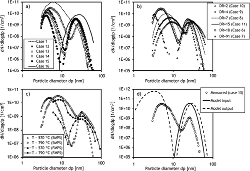
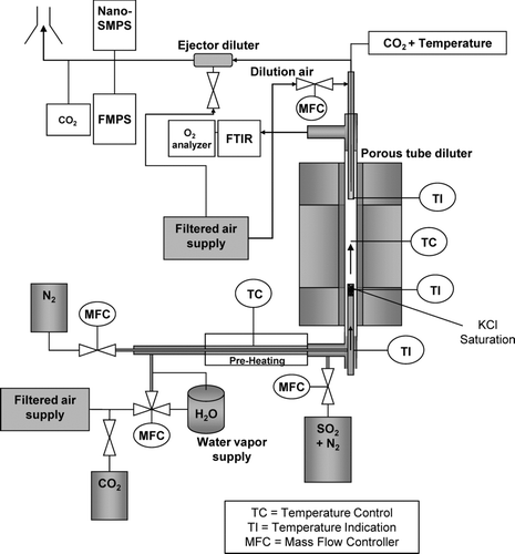
FIG. 7 Particle size distributions with (a) various K2SO4/KCl ratios, (b) various primary DRs, (c) various sampling locations, and (d) comparison of simulated and measured particle size distributions. The number concentrations are dilution-corrected.
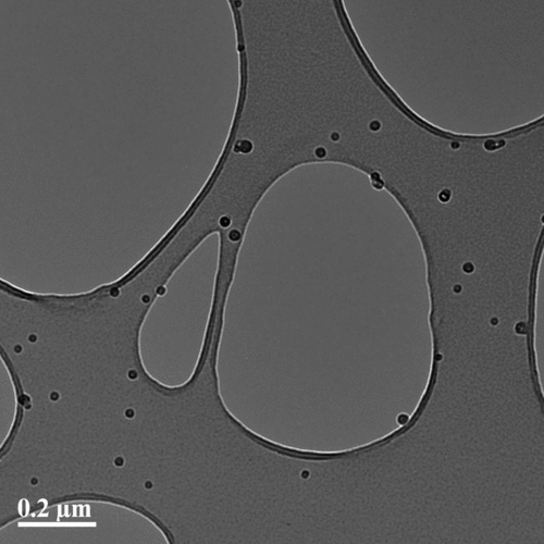
TABLE 2 Calculated cases of aerosol dynamics in the diluting probe, the mass fractions of KCl in the nucleation mode (PM0.01), and particle size distribution modes after the sampling line

FIG. 8 Simulated aerosol dynamics in the probe, simulation 5.

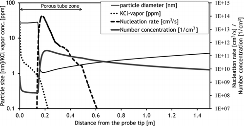
FIG. 8 Simulated aerosol dynamics in the probe, simulation 5.

FIG. 9 The mass size distributions of condensed KCl inside the diluter. (Color figure available online.)

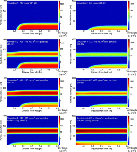
FIG. 9 The mass size distributions of condensed KCl inside the diluter. (Color figure available online.)
Supplemental material

uast_a_700741_sup_26740361.zip

Download Zip (344.7 KB)

Reprints and Corporate Permissions

Please note: Selecting permissions does not provide access to the full text of the article, please see our help page How do I view content?

To request a reprint or corporate permissions for this article, please click on the relevant link below:

Academic Permissions

Please note: Selecting permissions does not provide access to the full text of the article, please see our help page How do I view content?

Obtain permissions instantly via Rightslink by clicking on the button below:

If you are unable to obtain permissions via Rightslink, please complete and submit this Permissions form. For more information, please visit our Permissions help page.