1,213
Views
14
CrossRef citations to date
0
Altmetric
Original Articles

Experimental and Theoretical Investigations of the Effect of the Calibration Aerosol Material on the Counting Efficiencies of TSI 3790 Condensation Particle Counters

, &
Pages 11-21 | Received 19 Jan 2012, Accepted 11 Jul 2012, Published online: 27 Aug 2012

Figures & data

FIG. 1 Experimental setup for the calibration of the TSI 3790 CPCs.

FIG. 1 Experimental setup for the calibration of the TSI 3790 CPCs.

FIG. 2 Measured counting efficiencies of CPC#1 for PAO (squares) and graphite (circles) at four different temperature settings (the efficiencies at the nominal operating temperatures are shown on the top right panel). Symbols of different shadings correspond to test repetitions. The calibration points by TSI are also shown on the top right panel as filled rhombi.
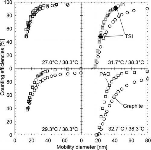
FIG. 2 Measured counting efficiencies of CPC#1 for PAO (squares) and graphite (circles) at four different temperature settings (the efficiencies at the nominal operating temperatures are shown on the top right panel). Symbols of different shadings correspond to test repetitions. The calibration points by TSI are also shown on the top right panel as filled rhombi.

FIG. 3 Left panels: measured counting efficiencies of two TSI 3790 CPCs set at different condenser temperatures (31.7°C versus 31.3°C) during manufacturer calibration. Different symbols indicate different calibration materials (PAO, C14, and C16), while different shadings correspond to repetitions with the same material. The numerically calculated counting efficiency curves for perfectly wettable particles at the two set temperatures are also shown. Right panels: comparison of measured counting efficiencies of CPC#1 for PAO (upper panel) and graphite (lower panel) with model predictions for contact angles of 0° (upper panel) and 10°C (lower panel). Calculated counting efficiencies are shown for both plug and fully developed laminar flow (parabolic velocity profile), as well as for a constant temperature gradient at the condenser inlet (assuming that the temperature at the centerline is 2°C higher than the condenser wall temperature).
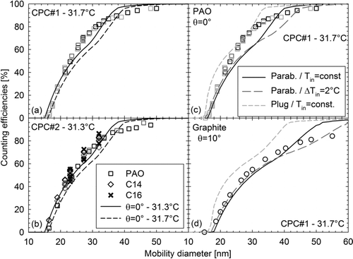
FIG. 3 Left panels: measured counting efficiencies of two TSI 3790 CPCs set at different condenser temperatures (31.7°C versus 31.3°C) during manufacturer calibration. Different symbols indicate different calibration materials (PAO, C14, and C16), while different shadings correspond to repetitions with the same material. The numerically calculated counting efficiency curves for perfectly wettable particles at the two set temperatures are also shown. Right panels: comparison of measured counting efficiencies of CPC#1 for PAO (upper panel) and graphite (lower panel) with model predictions for contact angles of 0° (upper panel) and 10°C (lower panel). Calculated counting efficiencies are shown for both plug and fully developed laminar flow (parabolic velocity profile), as well as for a constant temperature gradient at the condenser inlet (assuming that the temperature at the centerline is 2°C higher than the condenser wall temperature).

FIG. 4 Activation regions (bottom panel) of 17, 23, and 41 nm perfectly wettable particles at condenser temperatures of 31.3°C (black lines) and 31.7°C (gray lines). Symbols illustrate the expected width of the activation regions based on the measured counting efficiencies with CPC#1 and CPC#2 for PAO (the axial position of the symbols is arbitrarily selected). The top panel illustrates the counting efficiency as a function of the width of the activation region assuming fully developed laminar flow.
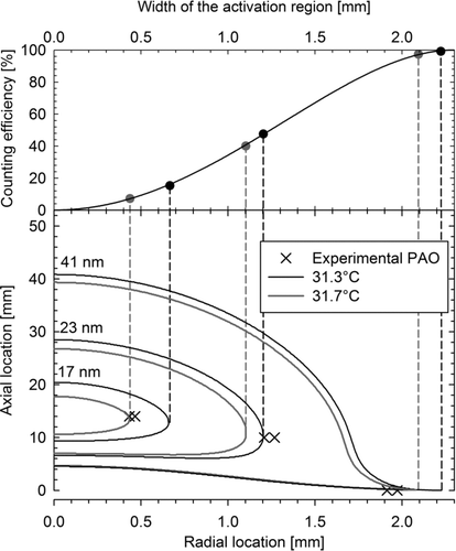
FIG. 4 Activation regions (bottom panel) of 17, 23, and 41 nm perfectly wettable particles at condenser temperatures of 31.3°C (black lines) and 31.7°C (gray lines). Symbols illustrate the expected width of the activation regions based on the measured counting efficiencies with CPC#1 and CPC#2 for PAO (the axial position of the symbols is arbitrarily selected). The top panel illustrates the counting efficiency as a function of the width of the activation region assuming fully developed laminar flow.

FIG. 5 Condensational growth of 17 nm (solid gray lines) and 41 nm (solid black lines) at the outermost radius of the corresponding activation regions. Dotted lines illustrate the Kelvin diameter at the conditions prevailing along the axial motion of the particle.
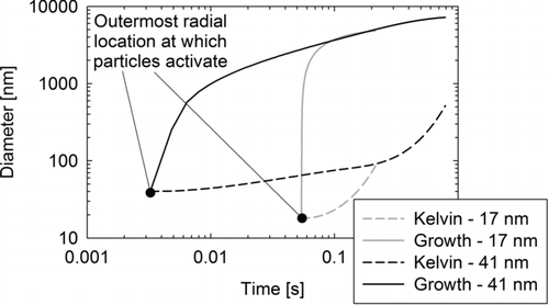
FIG. 5 Condensational growth of 17 nm (solid gray lines) and 41 nm (solid black lines) at the outermost radius of the corresponding activation regions. Dotted lines illustrate the Kelvin diameter at the conditions prevailing along the axial motion of the particle.

FIG. 6 Calculated contact angles as a function of counting efficiency for graphite (circles) and PAO (squares) particles, based on the experimental data from CPC#1. Different shadings correspond to different set condenser temperatures (saturator temperature was maintained at 38.3°C in all tests). The error bars illustrate the effect of a ±0.2°C uncertainty in the set temperatures on the calculated contact angles.
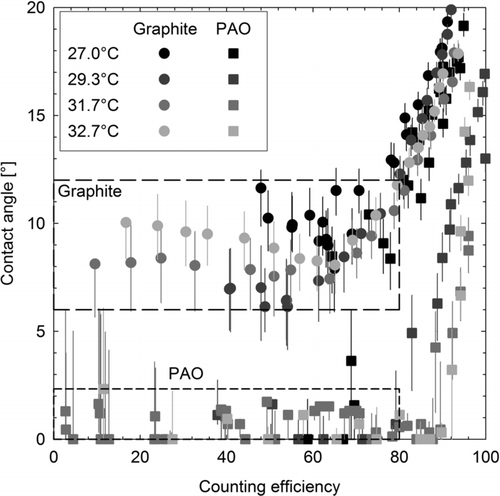
FIG. 6 Calculated contact angles as a function of counting efficiency for graphite (circles) and PAO (squares) particles, based on the experimental data from CPC#1. Different shadings correspond to different set condenser temperatures (saturator temperature was maintained at 38.3°C in all tests). The error bars illustrate the effect of a ±0.2°C uncertainty in the set temperatures on the calculated contact angles.

FIG. 7 Calculated line tension as a function of the counting efficiency for graphite (circles) and PAO (squares) particles, based on the experimental data from CPC#1. Different shadings correspond to different set condenser temperatures (saturator temperature was maintained at 38.3°C in all tests). The error bars illustrate the effect of a ±0.2°C uncertainty in the set temperatures on the calculated line tensions. The contact angle was assumed to be 0.5°, as a zero value would result in an infinite energy barrier (Equation (S7) substituted into Equation (S6)). The inset shows the calculated line tensions plotted against the mobility diameter.
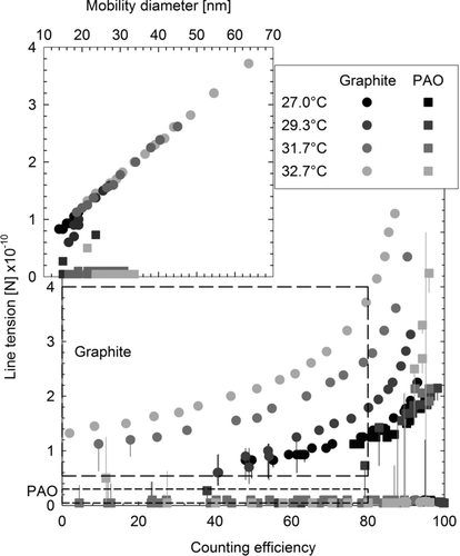
FIG. 7 Calculated line tension as a function of the counting efficiency for graphite (circles) and PAO (squares) particles, based on the experimental data from CPC#1. Different shadings correspond to different set condenser temperatures (saturator temperature was maintained at 38.3°C in all tests). The error bars illustrate the effect of a ±0.2°C uncertainty in the set temperatures on the calculated line tensions. The contact angle was assumed to be 0.5°, as a zero value would result in an infinite energy barrier (Equation (S7) substituted into Equation (S6)). The inset shows the calculated line tensions plotted against the mobility diameter.

FIG. 8 Numerically calculated counting efficiencies at contact angles of 0° (left-hand panel) and 10° (right-hand panel), for line tensions of 0 N, ±10–12 N and ±2 × 10–12 N.
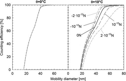
FIG. 8 Numerically calculated counting efficiencies at contact angles of 0° (left-hand panel) and 10° (right-hand panel), for line tensions of 0 N, ±10–12 N and ±2 × 10–12 N.

TABLE 1 Calculated saturator temperature (T in) required to detect 50% of 23 nm perfectly wettable particles entering the condenser at 31.3°C (d50 (θ = 0°) = 50%) and difference in the 50% cutoff size for 0° and 10° contact angle, for different working fluids. Also shown are the average vapor pressure (P vapor), temperature (T), liquid density (ρ l), surface tension (σ lg), saturation ratio (S), and critical radius (r*) across the envelope of the activation region of perfectly wettable 23 nm particles, as well as the maximum and minimum droplet size of the activated particles grown via condensation at the exit of the condenser

Supplemental material

uast_a_716174_sup_27794170.zip

Download Zip (6.2 MB)

Reprints and Corporate Permissions

Please note: Selecting permissions does not provide access to the full text of the article, please see our help page How do I view content?

To request a reprint or corporate permissions for this article, please click on the relevant link below:

Academic Permissions

Please note: Selecting permissions does not provide access to the full text of the article, please see our help page How do I view content?

Obtain permissions instantly via Rightslink by clicking on the button below:

If you are unable to obtain permissions via Rightslink, please complete and submit this Permissions form. For more information, please visit our Permissions help page.