Figures & data
FIG. 1 Relationships between impact velocities (Vi ) and particle sizes (Da or D va) for various particle impact phenomena (based on the paradigm originally proposed by Klinkov et al. [Citation2005]). Extreme regimes include erosion, cold spray, and hypervelocity impacts (Klinkov et al. Citation2005). Particle geometric diameters for each phenomena given in Klinkov et al. (Citation2005) are converted to Da by assuming that particle density is 1.5 g cm−3. The impact velocity-size relationships in AMS (black circles), MOUDI (open circles), and ELPI (gray circles) systems are shown as examples. Data for AMS, MOUDI, and ELPI were taken from Takegawa et al. (Citation2005), Marple et al. (Citation1991), and Keskinen et al. (Citation1992), respectively. For MOUDI and ELPI, particle diameters correspond to the 50% cut point Da at each stage in MOUDI and ELPI. The area enclosed by thick dashed black lines corresponds to the regime of the aerosol sampling techniques (e.g., Aerodyne AMS).
![FIG. 1 Relationships between impact velocities (Vi ) and particle sizes (Da or D va) for various particle impact phenomena (based on the paradigm originally proposed by Klinkov et al. [Citation2005]). Extreme regimes include erosion, cold spray, and hypervelocity impacts (Klinkov et al. Citation2005). Particle geometric diameters for each phenomena given in Klinkov et al. (Citation2005) are converted to Da by assuming that particle density is 1.5 g cm−3. The impact velocity-size relationships in AMS (black circles), MOUDI (open circles), and ELPI (gray circles) systems are shown as examples. Data for AMS, MOUDI, and ELPI were taken from Takegawa et al. (Citation2005), Marple et al. (Citation1991), and Keskinen et al. (Citation1992), respectively. For MOUDI and ELPI, particle diameters correspond to the 50% cut point Da at each stage in MOUDI and ELPI. The area enclosed by thick dashed black lines corresponds to the regime of the aerosol sampling techniques (e.g., Aerodyne AMS).](/cms/asset/96ff051c-97bc-45af-9a34-af541461bb32/uast_a_763895_o_f0001g.gif)
FIG. 2 V iy calculated for the impact of NaCl particles on the W surface as a function of their yield stresses.
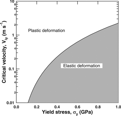
TABLE 1 COR predicted by the T1990 model as a function of σy
TABLE 2 Summary of the hydrodynamic simulations of liquid and solid particle impact
FIG. 3 A qualitative description of the stress-strain characteristics (von Mises model) used in the AUTODYN simulations.
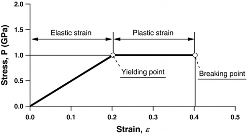
FIG. 4 Simulation results of the AN particle impact for the case of AN_case1. (a) The temporal evolutions of KE (black line) and IE (gray line) of the AN particle. (b) Pressure and temperature distributions of the AN particle and W surface at t = 1.0 ns.
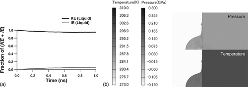
FIG. 5 Simulation results of the impact of NaCl particles. (a; left panel) Temporal evolutions of fractional contribution of KE (thick solid lines) and IE (thin dashed lines) for the cases NaCl_case1 (σy = 1.0 GPa). (a; right panel) Temporal evolutions of fractional contribution of ThW (thick solid lines) and IEP (thin dashed lines) for the cases NaCl_case1. (b; left panel) Temporal evolutions of fractional contribution of KE (solid lines) and IE (dashed lines) of the NaCl particle for the cases NaCl_case3 (σy = 0.1 GPa) (black) and NaCl_case4 (σy = 0.02 GPa) (shaded). (b; right panel) Temporal evolutions of fractional contribution of ThW (thick solid lines) and IEP (thin dashed lines) for the cases NaCl_case3 (black) and NaCl_case4 (gray).
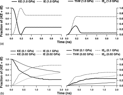
FIG. 6 Simulated profiles of (a) pressure, (b) temperature, (c) effective plastic strain, and (d) material status at t = 0.25 and 1.0 ns for the case of NaCl_case1 (σy = 1.0 GPa). The black area in the material status map is defined as the region that underwent failure due to large deformations.
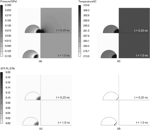
FIG. 7 Simulated profiles of (a) pressure and temperature, and (b) effective plastic strain and material status at t = 1.0 ns for the case NaCl_case4 (σy = 0.02 GPa). The black area in the material status map is defined as the region that underwent failure due to large deformations.
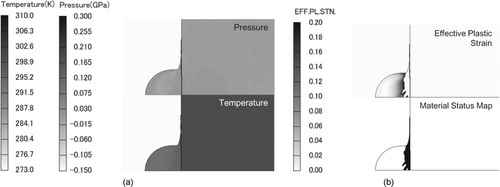
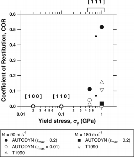
FIG. 8 Dependence of COR on σy
calculated using AUTODYN and T1990 model. Filled markers indicate the AUTODYN simulation results assuming 0.2 of ![]()
