1,245
Views
7
CrossRef citations to date
0
Altmetric
Original Articles

Investigation of Aerosol Penetration Through Individual Protective Equipment in Elevated Wind Conditions

, , &
Pages 705-713 | Received 07 Jan 2013, Accepted 17 Feb 2013, Published online: 01 Apr 2013

Figures & data

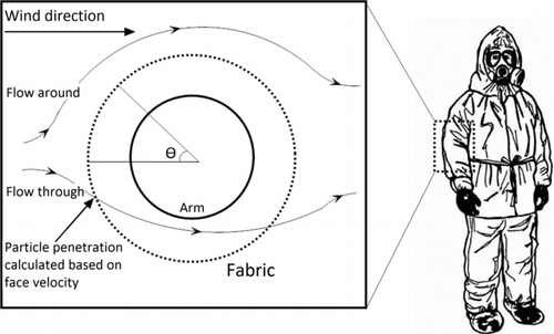
Figure 1 FIG. 1 Approach to modeling the component test: the sleeve is modeled as a rigid permeable cylinder, with a solid inner cylinder representing an appendage.
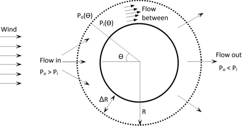
Figure 2 FIG. 2 Illustration of the potential flow model, adapted from Li et al. (Citation2001).
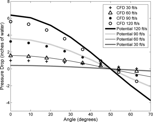
Figure 3 FIG. 3 Pressure drop across fabric predicted by potential flow and the numerical model plotted at four different free stream velocity values.
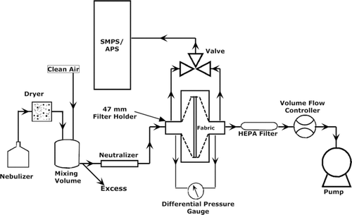
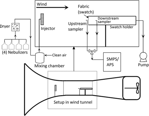
Figure 4 FIG. 4 Schematic diagram of the bench-top test setup used for fabric penetration measurements as a function of particle size and face velocity.
Figure 5 FIG. 5 Swatch test setup in wind tunnel. The wind-tunnel test section is 4 feet wide and 3 feet tall.
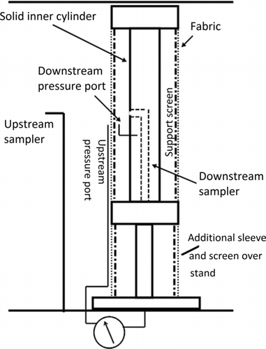
Figure 6 FIG. 6 Component test setup. The wind-tunnel injection and sampling system are identical to that of the swatch holder setup.
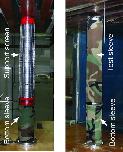
Figure 7 FIG. 7 Component holder with fabric support screen and additional sleeve covering the stand at the bottom, and full component test with sleeve. (Color figure available online.)
Figure 8 FIG. 8 Pressure drop measurements at θ = 0 compared to the potential flow model.
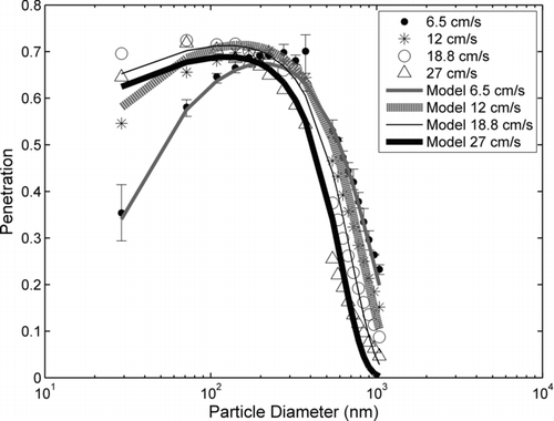
Figure 9 FIG. 9 Penetrations obtained from bench-top measurements for four different face velocities. The error bars represent the range of penetration values for five different fabric pieces. Measurement errors were similar for all face velocity cases and are only shown for the 6.5 cm s-1 case. These experimental results were used to determine the variables B1B4 in EquationEquation (4). The predictions of the penetration model using the variables B1B4 are shown.
Figure 9 FIG. 9 Penetrations obtained from bench-top measurements for four different face velocities. The error bars represent the range of penetration values for five different fabric pieces. Measurement errors were similar for all face velocity cases and are only shown for the 6.5 cm s-1 case. These experimental results were used to determine the variables B1–B4 in EquationEquation (4)(4) . The predictions of the penetration model using the variables B1–B4 are shown.
Figure 10 FIG. 10 Contribution of filtration mechanisms for 6.5 cm s−1 face velocity.
Figure 11 FIG. 11 Contribution of filtration mechanisms for 27 cm s−1 face velocity.
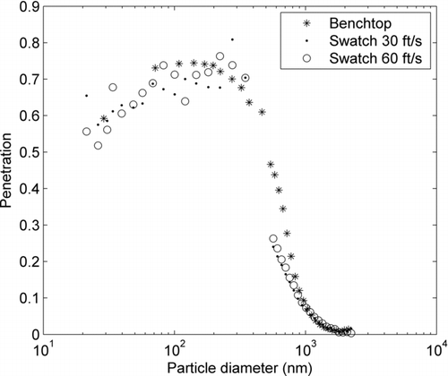
Figure 12 FIG. 12 Wind-tunnel swatch test results for two different free stream velocities (30 and 60 ft/s) plotted with bench-top data of equivalent face velocity (27 cm s−1; based on the sample flow through the swatch).
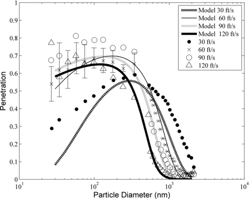
Figure 13 FIG. 13 Component penetration predicted by the model. The error bars represent the standard deviation of penetration results with three different sleeve samples. Measurement uncertainties were similar for all velocity cases and are only shown for one test case (60 ft/s).

Reprints and Corporate Permissions

Please note: Selecting permissions does not provide access to the full text of the article, please see our help page How do I view content?

To request a reprint or corporate permissions for this article, please click on the relevant link below:

Academic Permissions

Please note: Selecting permissions does not provide access to the full text of the article, please see our help page How do I view content?

Obtain permissions instantly via Rightslink by clicking on the button below:

If you are unable to obtain permissions via Rightslink, please complete and submit this Permissions form. For more information, please visit our Permissions help page.