778
Views
10
CrossRef citations to date
0
Altmetric
Original Articles

Evaluation of a Perpendicular Inlet for Airborne Sampling of Interstitial Submicron Black-Carbon Aerosol

, , , , , & show all
Pages 1066-1072 | Received 20 Mar 2013, Accepted 23 Jun 2013, Published online: 01 Aug 2013

Figures & data

FIG. 1 (Top) Diagram of the near-isokinetic inlet with letters denoting the primary diffuser (a), secondary diffuser (b), flow to the SP2 (c), exhaust port (d), and differential pressure ports (e) taken from Schwarz et al. (Citation2006). (Bottom) Diagram of the perpendicular inlet with letters denoting the inlet port (a) in the flat plate and on the pylon and the inlet line connecting to the SP2 (b). Both inlets are shown with the same scale and are configured with a similar pylon design with the sampling points separated from the fuselage by 30 cm.
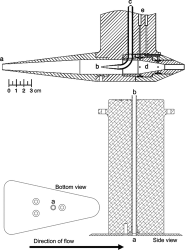
FIG. 1 (Top) Diagram of the near-isokinetic inlet with letters denoting the primary diffuser (a), secondary diffuser (b), flow to the SP2 (c), exhaust port (d), and differential pressure ports (e) taken from Schwarz et al. (Citation2006). (Bottom) Diagram of the perpendicular inlet with letters denoting the inlet port (a) in the flat plate and on the pylon and the inlet line connecting to the SP2 (b). Both inlets are shown with the same scale and are configured with a similar pylon design with the sampling points separated from the fuselage by 30 cm.

FIG. 2 Sample of in-cloud and out-of-cloud data averaged to 1 min for the near-isokinetic inlet (a) and the perpendicular inlet (b) including VIPS ice probe counts, SID3 ice probe counts, 2DS particle counts (all plotted on right axis), and BC mass loading (left axis). Bars show standard deviation of 1-s data. In-cloud sampling is indicated by gray shading as defined by periods when any two of the cloud probes indicated greater than 10 particles/(L of air). (Color figure available online.)
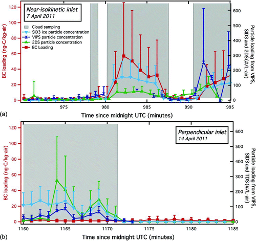
FIG. 2 Sample of in-cloud and out-of-cloud data averaged to 1 min for the near-isokinetic inlet (a) and the perpendicular inlet (b) including VIPS ice probe counts, SID3 ice probe counts, 2DS particle counts (all plotted on right axis), and BC mass loading (left axis). Bars show standard deviation of 1-s data. In-cloud sampling is indicated by gray shading as defined by periods when any two of the cloud probes indicated greater than 10 particles/(L of air). (Color figure available online.)

FIG. 3 Normalized histograms of observed incandescence ratios for large (>10 fg) BC-containing particles (a) and normalized mass distributions (b) observed with the near-isokinetic inlet in clouds and out of clouds and with the perpendicular inlet in clouds and out of clouds. Error bars in (b) show the standard deviation of individual distributions calculated for each flight at altitudes above 8 km. Data from all four flights with the near-isokinetic inlet and eight flights with the perpendicular inlet are included. Total particle counts were 1.2 × 10⁵ and 9.5 × 10⁴ for the near isokinetic inlet in and out of clouds, respectively, and 2.6 × 10⁵ and 5.1 × 10⁵ and for the perpendicular inlet in and out of clouds, respectively. Each curve was normalized to have equal peak values in the diameter range shown. (Color figure available online.)
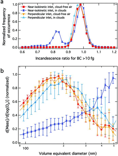
FIG. 3 Normalized histograms of observed incandescence ratios for large (>10 fg) BC-containing particles (a) and normalized mass distributions (b) observed with the near-isokinetic inlet in clouds and out of clouds and with the perpendicular inlet in clouds and out of clouds. Error bars in (b) show the standard deviation of individual distributions calculated for each flight at altitudes above 8 km. Data from all four flights with the near-isokinetic inlet and eight flights with the perpendicular inlet are included. Total particle counts were 1.2 × 10⁵ and 9.5 × 10⁴ for the near isokinetic inlet in and out of clouds, respectively, and 2.6 × 10⁵ and 5.1 × 10⁵ and for the perpendicular inlet in and out of clouds, respectively. Each curve was normalized to have equal peak values in the diameter range shown. (Color figure available online.)

FIG. 4 Composite vertical profiles of BC mass loadings from averages over 1000-m altitude bins observed under clear sky conditions using the near-isokinetic inlet (squares) and the perpendicular inlet (triangles) during the MACPEX mission. Bars show the standard deviation of the individual profile data points at each altitude interval. Seven profiles were obtained using the near-isokinetic inlet and 16 were obtained using the perpendicular inlet. Also shown for comparison (solid and dashed lines) are vertical profiles from two flights in 2004 using the near isokinetic inlet aboard the WB-57F (Schwarz et al. Citation2006). (Color figure available online.)
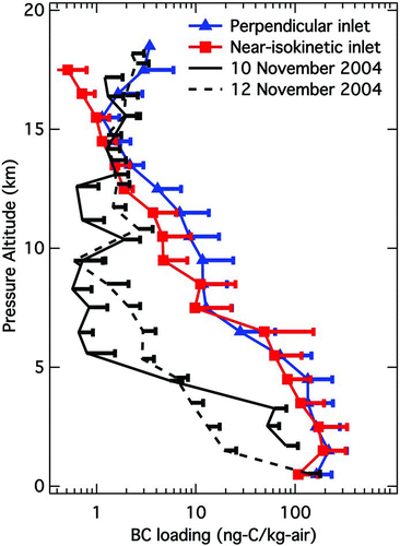
FIG. 4 Composite vertical profiles of BC mass loadings from averages over 1000-m altitude bins observed under clear sky conditions using the near-isokinetic inlet (squares) and the perpendicular inlet (triangles) during the MACPEX mission. Bars show the standard deviation of the individual profile data points at each altitude interval. Seven profiles were obtained using the near-isokinetic inlet and 16 were obtained using the perpendicular inlet. Also shown for comparison (solid and dashed lines) are vertical profiles from two flights in 2004 using the near isokinetic inlet aboard the WB-57F (Schwarz et al. Citation2006). (Color figure available online.)

Reprints and Corporate Permissions

Please note: Selecting permissions does not provide access to the full text of the article, please see our help page How do I view content?

To request a reprint or corporate permissions for this article, please click on the relevant link below:

Academic Permissions

Please note: Selecting permissions does not provide access to the full text of the article, please see our help page How do I view content?

Obtain permissions instantly via Rightslink by clicking on the button below:

If you are unable to obtain permissions via Rightslink, please complete and submit this Permissions form. For more information, please visit our Permissions help page.