Figures & data
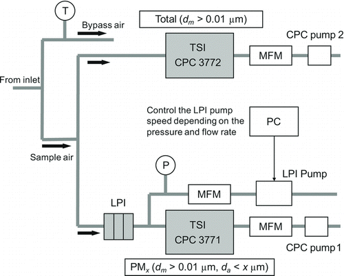
FIG. 1 Schematic diagram of LPI-CPCs (MFM: mass flow meter; T: temperature sensor; P: pressure sensor). The pressure sensors incorporated in the 3771 and 3772 (not explicitly shown) are used to measure the pressure downstream and upstream of the LPI, respectively. The additional pressure sensor downstream of the LPI is used for backup and checking consistency.

TABLE 1 Dimensions of the low-pressure impactor (LPI)
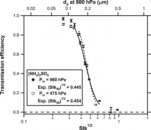
FIG. 2 Transmission efficiency of the LPI as a function of the square root of Stk for inlet pressures (P in) of 980 and 475 hPa. The solid and dashed lines represent the fitting results for 980 and 475 hPa, respectively. Corresponding aerodynamic diameters at 980 hPa are shown on the top axis.

TABLE 2 Laboratory evaluation of the LPI stage 1a
FIG. 3 Dependence of the transmission efficiency of the LPI on P in for particles with a mobility diameter (dm ) of 0.05 μm obtained before the aircraft measurement campaign (laboratory experiment [1]). The solid line represents the fitting result. The calculated cutoff diameter (da 50,calc) and volumetric flow rate through the LPI ranged from 0.23 to 0.19 μm and from 4 to 9 L min−1, respectively, at inlet pressures ranging from 380 to 980 hPa.
![FIG. 3 Dependence of the transmission efficiency of the LPI on P in for particles with a mobility diameter (dm ) of 0.05 μm obtained before the aircraft measurement campaign (laboratory experiment [1]). The solid line represents the fitting result. The calculated cutoff diameter (da 50,calc) and volumetric flow rate through the LPI ranged from 0.23 to 0.19 μm and from 4 to 9 L min−1, respectively, at inlet pressures ranging from 380 to 980 hPa.](/cms/asset/326ca635-0464-46e7-bef2-20538b1ebd83/uast_a_822462_o_f0003g.gif)
TABLE 3 Possible errors (1σ)a
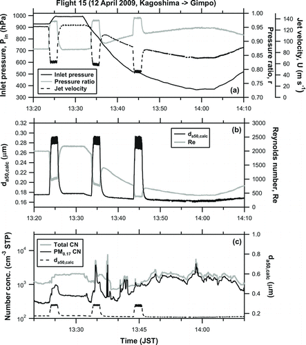
FIG. 4 Time series of some key variables of the LPI, including (a) P in, jet velocity (U), and pressure ratio (r); (b) Reynolds number (Re), calculated cutoff diameter (da 50,calc); and (c) total CN concentration, and PM0.17 CN concentration during flight 15 on 12 April 2009. The data are 1-s averages.

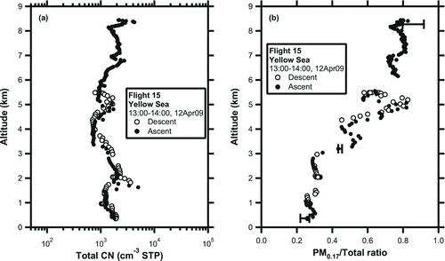
FIG. 5 Vertical profiles of (a) total CN concentration and (b) the ratio of PM0.17 to the total CN concentration (PM0.17/total ratio) observed over the Yellow Sea during flight 15. Open and solid circles represent the aircraft descent and ascent data, respectively. The data are 10-s averages. Error bars for some selected data points (at ∼1000, 700, 350 hPa) are shown. See Section 3.2 for details of the error estimate.
