Figures & data
FIG. 1 Theoretical APM transfer functions when the velocity profile of the aerosol flow is assumed uniform (solid line) and parabolic (dashed line). The transfer functions for λc = 0.47 are shown in this figure. (Reproduced from Weingartner et al. (Citation2011) with permission of John Wiley & Sons, Inc.)
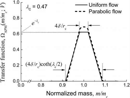
FIG. 2 Typical contours of m c (solid curves) and λc (dashed curves) in the (ω, V) plane. The rectangle ABCD indicates the operation region.
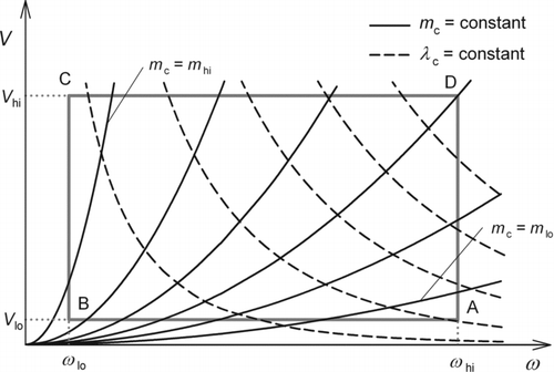
FIG. 3 Schematic illustration of the operation region in the (m c, λc) plane with both axes represented in logarithmic scale. The distorted parallelogram ABCD corresponds to the rectangle ABCD in Figure 2.
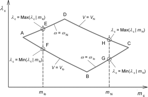
FIG. 4 Regions in the (r c, δ) plane satisfying the conditions [RA1], [RA2], [RB1], and [RB2] for (a) l = 0.003 s/mm2, (b) 0.01 s/mm2, (c) 0.02 s/mm2, and (d) 0.04 s/mm2. The hatched areas indicate the regions in which all four conditions are satisfied. The crossmark in panel (c) represents the combination of the design parameters finally selected. Note that [RA1] and [RA2] represent the requirements, derived from Inequalities Equation(13) and (14) respectively, on the minimum and maximum particle masses that can be classified by the APM, while [RB1] and [RB2] the requirements, both derived from Inequality Equation(15), that the resolution at m c = m lo and m c = m hi, respectively, be larger than R lo (= 0.5).
![FIG. 4 Regions in the (r c, δ) plane satisfying the conditions [RA1], [RA2], [RB1], and [RB2] for (a) l = 0.003 s/mm2, (b) 0.01 s/mm2, (c) 0.02 s/mm2, and (d) 0.04 s/mm2. The hatched areas indicate the regions in which all four conditions are satisfied. The crossmark in panel (c) represents the combination of the design parameters finally selected. Note that [RA1] and [RA2] represent the requirements, derived from Inequalities Equation(13) and (14) respectively, on the minimum and maximum particle masses that can be classified by the APM, while [RB1] and [RB2] the requirements, both derived from Inequality Equation(15), that the resolution at m c = m lo and m c = m hi, respectively, be larger than R lo (= 0.5).](/cms/asset/27f179c6-a4d8-4d0b-9001-459399263e57/uast_a_827323_o_f0004g.gif)
Table 1 Comparison between the compact APM developed in the present study and the Model 3600 APM
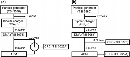
FIG. 5 Operation region of the compact APM constructed in the present study (distorted parallelogram). The hatched area indicates the region in which Requirements A, B, and C are all satisfied. The symbols ○, □, and ▪ represent the points on which APM spectra were experimentally obtained, where ○ represents an experiment conducted in configuration (a) with PSL particles used as test particles; □ in configuration (b) with PSL particles; and ▪ in configuration (b) with Santovac oil particles. See Figure 6 for configurations (a) and (b).
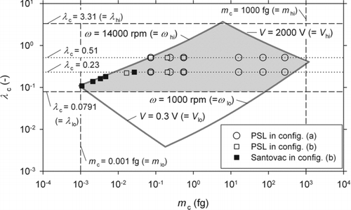
FIG. 7 APM spectra for (a) PSL particles with λc = 0.51, (b) PSL particles with λc = 0.23, and (c) Santovac oil particles. Experimental spectra are shown with symbols, calculated spectra obtained by the least square fitting method shown with solid curves, and theoretically predicted spectra shown with dotted curves. Associated with each experimental spectrum is the values of the DMA-classified diameter and of the number-averaged mass. For spectra of Santovac oil particles, the values of λc are also shown.
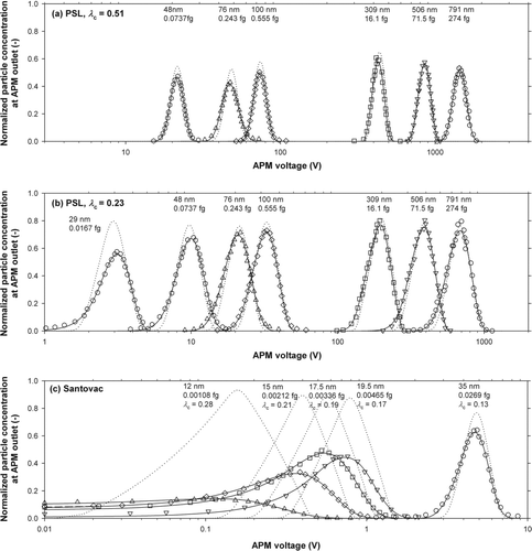
FIG. 8 Ratio of the number-averaged mass obtained experimentally to that predicted theoretically. The theoretically predicted mass values were based on the assumption that particles, including NaCl particles in the experiment with the Model 3600 APM, are spherical.
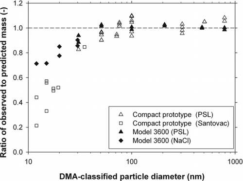
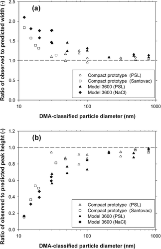
FIG. 9 Ratios of (a) the full width at half maximum and (b) the peak height of the experimental spectra to those of the theoretically predicted spectra.
