1,336
Views
2
CrossRef citations to date
0
Altmetric
Original Articles

Anisokinetic Shrouded Nozzle System for Constant Low-Flow Rate Aerosol Sampling from Turbulent Duct Flow

&
Pages 90-98 | Received 24 Jan 2013, Accepted 01 Oct 2013, Published online: 13 Dec 2013

Figures & data

FIG. 1 Photograph of a shrouded nozzle sampling system showing the shrouded inlet piece, the bend, and the outlet tube with the mounting assembly.
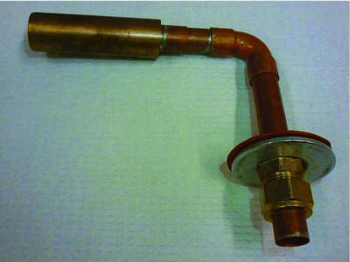
FIG. 1 Photograph of a shrouded nozzle sampling system showing the shrouded inlet piece, the bend, and the outlet tube with the mounting assembly.

FIG. 2 Schematics (left) of a side view of a section through the centerline of the shrouded inlet and (right) of an end view of the inlet. Dimensions of defined parameters are also given. This figure is not drawn to scale.
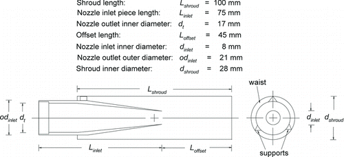
FIG. 2 Schematics (left) of a side view of a section through the centerline of the shrouded inlet and (right) of an end view of the inlet. Dimensions of defined parameters are also given. This figure is not drawn to scale.

FIG. 3 Isokinetic buttonhook nozzle transport efficiencies versus particle diameter for the nominal air speeds of 2.2, 5.3, 8.8, and 9.0 m/s.
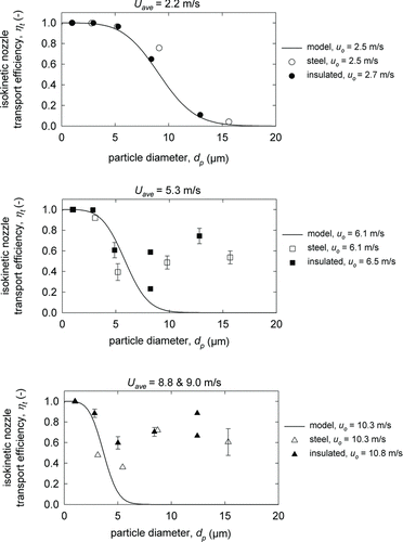
FIG. 3 Isokinetic buttonhook nozzle transport efficiencies versus particle diameter for the nominal air speeds of 2.2, 5.3, 8.8, and 9.0 m/s.

TABLE 1 Summary of absolute model-measurement error magnitudes for each component of the shrouded nozzle sampling system*

FIG. 4 Shrouded nozzle transport efficiencies versus particle diameter for the nominal air speeds of 2.2, 5.3, and 8.8 m/s.
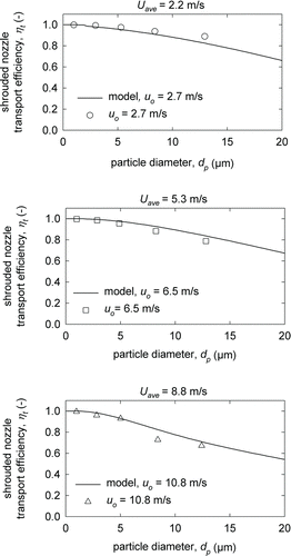
FIG. 4 Shrouded nozzle transport efficiencies versus particle diameter for the nominal air speeds of 2.2, 5.3, and 8.8 m/s.

FIG. 5 Total aspiration efficiencies for the shrouded nozzle versus particle diameter for the nominal air speeds of 2.2, 5.3, and 8.8 m/s. The model utilizes EquationEquation (9) with individual aspiration efficiencies for the shroud and inlet nozzle calculated by EquationEquation (3).
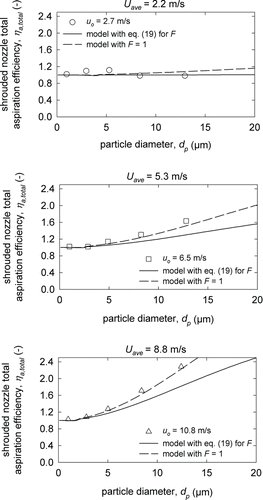
FIG. 5 Total aspiration efficiencies for the shrouded nozzle versus particle diameter for the nominal air speeds of 2.2, 5.3, and 8.8 m/s. The model utilizes EquationEquation (9) with individual aspiration efficiencies for the shroud and inlet nozzle calculated by EquationEquation (3).

FIG. 6 Total transmission efficiencies for the shrouded nozzle versus particle diameter for the nominal air speeds of 2.2, 5.3, and 8.8 m/s. The model includes the empirical model for transport efficiencies and EquationEquations (3) and Equation(9) with F = 1 for total aspiration efficiencies.
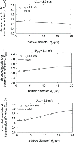
FIG. 6 Total transmission efficiencies for the shrouded nozzle versus particle diameter for the nominal air speeds of 2.2, 5.3, and 8.8 m/s. The model includes the empirical model for transport efficiencies and EquationEquations (3) and Equation(9) with F = 1 for total aspiration efficiencies.
Supplemental material

SI_for_Shrouded_Nozzle__AST-MS-2013-012.R2_.pdf.zip

Download Zip (279 KB)

Reprints and Corporate Permissions

Please note: Selecting permissions does not provide access to the full text of the article, please see our help page How do I view content?

To request a reprint or corporate permissions for this article, please click on the relevant link below:

Academic Permissions

Please note: Selecting permissions does not provide access to the full text of the article, please see our help page How do I view content?

Obtain permissions instantly via Rightslink by clicking on the button below:

If you are unable to obtain permissions via Rightslink, please complete and submit this Permissions form. For more information, please visit our Permissions help page.