1,081
Views
14
CrossRef citations to date
0
Altmetric
Regular Articles

Portable Planar DMA: Development and Tests

, , , &
Pages 251-260 | Received 13 Dec 2012, Accepted 20 Oct 2013, Published online: 21 Jan 2014

Figures & data

FIG. 1 Air velocity field in the planar DMA at P = 101,325 Pa, T = 20°C, the height in the z-direction is 5 mm and the width in the y-direction is 40 mm. The total flow rate in the DMA was 2 l/min. The velocity is coded according to the scale bar on the right in m/s. The arrow indicates the direction of flow.
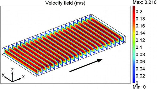
FIG. 1 Air velocity field in the planar DMA at P = 101,325 Pa, T = 20°C, the height in the z-direction is 5 mm and the width in the y-direction is 40 mm. The total flow rate in the DMA was 2 l/min. The velocity is coded according to the scale bar on the right in m/s. The arrow indicates the direction of flow.

FIG. 2 Velocity profile (a) u x at x = 0.04 m and y = 0.02 m and (b) u x at x = 0.04 m and z = 0.0025 m for the example in Figure 1.
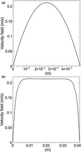
FIG. 2 Velocity profile (a) u x at x = 0.04 m and y = 0.02 m and (b) u x at x = 0.04 m and z = 0.0025 m for the example in Figure 1.

FIG. 3 (a) Trajectories are shown for 5, 50, and 500 nm singularly charged aerosol particles in the air velocity field of the planar DMA at P = 101,325 Pa, T = 20°C. The separation chamber height is 5 mm and the width is 40 mm. The cross-section at y = 0.02 m is shown. The sheath flow rate Q sh is 1.8 l/min, the aerosol flow rate Q a is 0.2 l/min, and the voltage difference across the DMA electrodes is 220 V. Particles are introduced from the bottom left. Under these conditions it can be seen that the 50 nm particles are selected and sent to the outlet while particles smaller or larger are lost to the opposite electrode or sheath flow, respectively. The velocity is coded according to the scale bar on the right in m/s. The vertical scale (z) and the horizontal scale (x) are in meters. (b) The same as in (a) but magnified at the aerosol outlet.
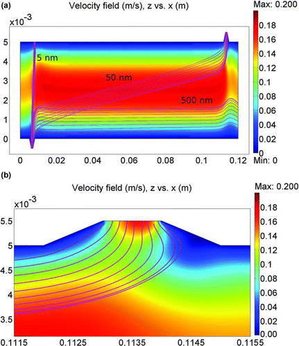
FIG. 3 (a) Trajectories are shown for 5, 50, and 500 nm singularly charged aerosol particles in the air velocity field of the planar DMA at P = 101,325 Pa, T = 20°C. The separation chamber height is 5 mm and the width is 40 mm. The cross-section at y = 0.02 m is shown. The sheath flow rate Q sh is 1.8 l/min, the aerosol flow rate Q a is 0.2 l/min, and the voltage difference across the DMA electrodes is 220 V. Particles are introduced from the bottom left. Under these conditions it can be seen that the 50 nm particles are selected and sent to the outlet while particles smaller or larger are lost to the opposite electrode or sheath flow, respectively. The velocity is coded according to the scale bar on the right in m/s. The vertical scale (z) and the horizontal scale (x) are in meters. (b) The same as in (a) but magnified at the aerosol outlet.

FIG. 4 (a) Air molecule streamlines in the DMA as in Figure 3a. (b) Electric field strength contour plot in the DMA for the area shown in Figure 3b. The normal electric field near the aerosol outlet is shown on a magnified scale.
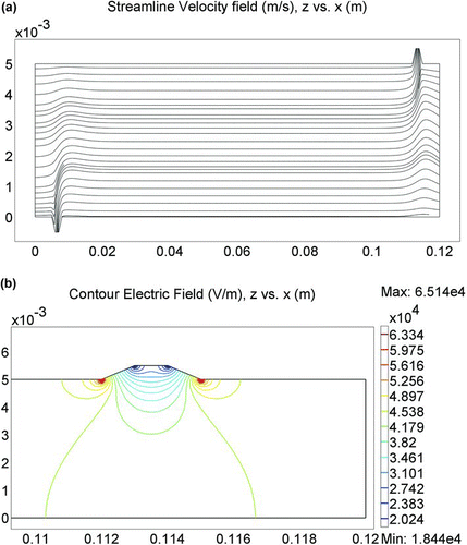
FIG. 4 (a) Air molecule streamlines in the DMA as in Figure 3a. (b) Electric field strength contour plot in the DMA for the area shown in Figure 3b. The normal electric field near the aerosol outlet is shown on a magnified scale.

FIG. 5 (a) An example of an apparatus function for the planar DMA Ω(dp ) for monodisperse particles of 200 nm with sheath flow Q sh = 1.8 l/min and aerosol flow Q a = 0.2 l/min. The markers show numerical calculations based on particle trajectories used in the model, while the solid curve shows an exponential parameterized fit function for each branch of the transfer function. (b) As in (a) but for monodisperse particles of 50 nm. (c) As in (a) but for monodisperse particles of 5 nm. (d) An example of the change in DMA resolution Δlogdp = log(d2 /d1 ) as a function of flow rate ratio. Data points show the results of calculations for the current geometry. Q sh is the sheath flow rate and Q a is the aerosol flow rate. d1 and d2 are the sizes corresponding to 50% of the transfer function height such that log(d2 /d1 ) is the full-width half-maximum in logarithmic scale. Circles: 5 nm; squares: 50 nm, and diamonds: 200 nm.
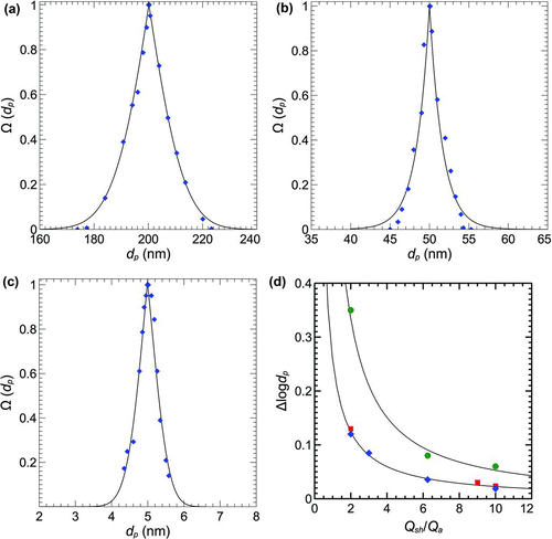
FIG. 5 (a) An example of an apparatus function for the planar DMA Ω(dp ) for monodisperse particles of 200 nm with sheath flow Q sh = 1.8 l/min and aerosol flow Q a = 0.2 l/min. The markers show numerical calculations based on particle trajectories used in the model, while the solid curve shows an exponential parameterized fit function for each branch of the transfer function. (b) As in (a) but for monodisperse particles of 50 nm. (c) As in (a) but for monodisperse particles of 5 nm. (d) An example of the change in DMA resolution Δlogdp = log(d2 /d1 ) as a function of flow rate ratio. Data points show the results of calculations for the current geometry. Q sh is the sheath flow rate and Q a is the aerosol flow rate. d1 and d2 are the sizes corresponding to 50% of the transfer function height such that log(d2 /d1 ) is the full-width half-maximum in logarithmic scale. Circles: 5 nm; squares: 50 nm, and diamonds: 200 nm.

FIG. 6 (a) Schematic cross-section of the planar DMA at [x, 0.02 m, z]. (b) Schematic of the PMC500 assembly. AF is an aerosol filter (Mitsubishi, Tokyo, Japan); Dpf is a differential pressure flow meter.

FIG. 6 (a) Schematic cross-section of the planar DMA at [x, 0.02 m, z]. (b) Schematic of the PMC500 assembly. AF is an aerosol filter (Mitsubishi, Tokyo, Japan); Dpf is a differential pressure flow meter.

FIG. 7 An example 100 nm monodisperse selection of atmospheric aerosol made by the PMC500. The aerosol and sheath flow were 0.3 and 3 l/min, respectively, both in the PMC500 DMA and in the Grimm SMPS.
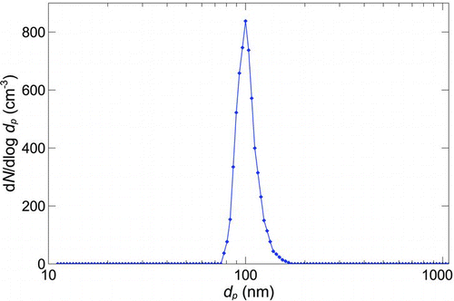
FIG. 7 An example 100 nm monodisperse selection of atmospheric aerosol made by the PMC500. The aerosol and sheath flow were 0.3 and 3 l/min, respectively, both in the PMC500 DMA and in the Grimm SMPS.

FIG. 8 The test setup.

FIG. 8 The test setup.

FIG. 9 A typical size distribution obtained with: (a) PSL particles of 100 nm selected with a 100 nm cut; (b) a typical size distribution obtained with NaCl particles of 150 nm selected with a 150 nm cut; (c) a typical size distribution obtained with NaCl particles of 30 nm selected with a 30 nm cut.
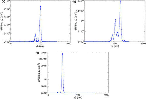
FIG. 9 A typical size distribution obtained with: (a) PSL particles of 100 nm selected with a 100 nm cut; (b) a typical size distribution obtained with NaCl particles of 150 nm selected with a 150 nm cut; (c) a typical size distribution obtained with NaCl particles of 30 nm selected with a 30 nm cut.

Reprints and Corporate Permissions

Please note: Selecting permissions does not provide access to the full text of the article, please see our help page How do I view content?

To request a reprint or corporate permissions for this article, please click on the relevant link below:

Academic Permissions

Please note: Selecting permissions does not provide access to the full text of the article, please see our help page How do I view content?

Obtain permissions instantly via Rightslink by clicking on the button below:

If you are unable to obtain permissions via Rightslink, please complete and submit this Permissions form. For more information, please visit our Permissions help page.