Figures & data
FIG. 1 Cross-sectional schematic of the thermodenuder constructed and used for this study.
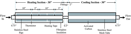
FIG. 2 (a) Thermodenuder centerline temperature profiles at unique temperature set points (T set) and a flow rate of 1 L min−1. Offline thermal probe measurement precision is 0.5°C. (b) Particle transmission efficiency through the thermodenuder compared to previously published values. Measurements correspond to 1 L min−1 flow through the instrument. The solid black line represents theoretical losses from Brownian diffusion.
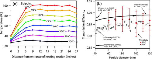
FIG. 3 Experimental setup for combined volatility and hygroscopicity measurements.
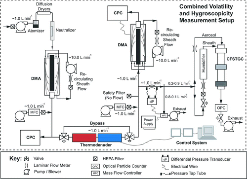
FIG. 4 Simulated thermodenuder geometry and fields for inlet monodisperse adipic acid aerosol with 1000 cm−3 concentration, 1.0 L min−1 flow rate and 60°C set point in the heating section. (a) Thermodenuder geometry with sample streamlines and gridding system. (b) Simulated sizes for a 66 nm inlet diameter aerosol as a function of distance from the centerline. (c) Simulated size for 155 nm inlet aerosol flowing at streamline A at 1, 10, and 100 times the nominal inlet concentration. (d) is similar to (c), but for streamline B. Contour plots of simulated organic vapor (e) saturation ratio, (f) concentration, and (g) formation rate, assuming the cooling section is an impermeable wall. (h), (i), and (j) are similar to (e), (f), and (g), respectively, but assuming the cooling section is a perfect sink of organic vapor.
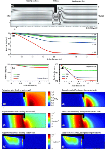
TABLE 1 Thermodynamic and transport properties for investigated compounds
FIG. 5 Example size distributions measured from the thermodenuder (solid lines) and bypass (dotted lines) at 40, 50, and 60°C for azelaic acid with initial size of approximately 85 nm. Note that particle loadings vary between experiments.
TABLE 2 Reference saturation vapor pressure (at 298 K) and ΔH. C* is calculated using properties from Table 1. Results of different model runs are identified by the surface tension (σ) source value and are also numbered consistently with Figure 7
FIG. 6 Thermodenuder model response overlaid with laboratory observations for each volatility measurement considered. Solid curves represent the model evaluated at one set of the optimized parameters from . The dashed curves are model evaluations made at the upper and lower bounds of the uncertainty ranges in the retrieved parameters. The points plotted indicate corresponding inlet and outlet mode diameter values. Starred points represented data that was fitted to the model. Open circles separate from the starred points are data affected by nonvolatile cores (and were not considered in the fitting procedure). Each set of curves and points represents measurements made at a particular temperature (indicated by the legend). Dashed curves indicate the uncertainty range of the model response, while keys shown in (c) and (f) apply to all six parts of the figure.
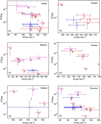
FIG. 7 Volatility parameters and sensitivity tests for select compounds compared against literature data. The dashed (blue) bars/points indicate values obtained from measurements with each one corresponding to different rows of . The darkest and medium grey (red and magenta) bars refer to literature values reported for solid and liquid phase data, respectively. Note that (b) excludes the outlier value from Cappa et al. (Citation2007). Plotted literature data (letters) correspond to sources as follows: A (Bilde et al. Citation2003), B (Booth et al. Citation2009), C (Booth et al. Citation2010), D (Booth et al. Citation2011), E (Cappa et al. Citation2007), F (Chattopadhyay et al. Citation2001), G (Pope et al. Citation2010), H (Riipinen et al. Citation2007), I (Saleh et al. Citation2009), J (Saleh et al. Citation2010), K (Salo et al. Citation2010), and L (Soonsin et al. Citation2010).