5,649
Views
74
CrossRef citations to date
0
Altmetric
Original Articles

Aerosol Measurement by Induced Currents

, , &
Pages 350-357 | Received 19 Sep 2013, Accepted 08 Dec 2013, Published online: 24 Feb 2014

Figures & data

FIG. 1 (a) Tube with length L and radius R where LR, and with grids on both ends, (b) tube with LR, (c) ring with LR, and (d) the tube of (b) split into two equal segments.

FIG. 1 (a) Tube with length L and radius R where L ≫ R, and with grids on both ends, (b) tube with L ≫ R, (c) ring with L ≪ R, and (d) the tube of (b) split into two equal segments.
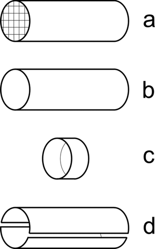
FIG. 2 Scheme of our new instrument. Similar previous instruments use a filter to capture the particles in a Faraday cup electrometer, whereas we use an open Faraday cage.

FIG. 2 Scheme of our new instrument. Similar previous instruments use a filter to capture the particles in a Faraday cup electrometer, whereas we use an open Faraday cage.

FIG. 3 Image of the partector with reference objects for size comparison.

FIG. 3 Image of the partector with reference objects for size comparison.

FIG. 4 Electrometer signal with 50 nm NaCl particles of a concentration of 1.7*104 pt/ccm (gray) and charging current (black) for different pulse settings.
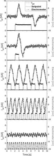
FIG. 4 Electrometer signal with 50 nm NaCl particles of a concentration of 1.7*104 pt/ccm (gray) and charging current (black) for different pulse settings.

FIG. 5 Determination of lower detection limit with 50 nm NaCl particles. Left: time series of signals measured by CPC and partector for decreasing dilution. Right: averaged values over each concentration step. The line is a guide to the eye. The partector signal deviates from the 1:1 line for low concentrations due to instrument noise.
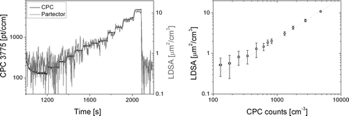
FIG. 5 Determination of lower detection limit with 50 nm NaCl particles. Left: time series of signals measured by CPC and partector for decreasing dilution. Right: averaged values over each concentration step. The line is a guide to the eye. The partector signal deviates from the 1:1 line for low concentrations due to instrument noise.
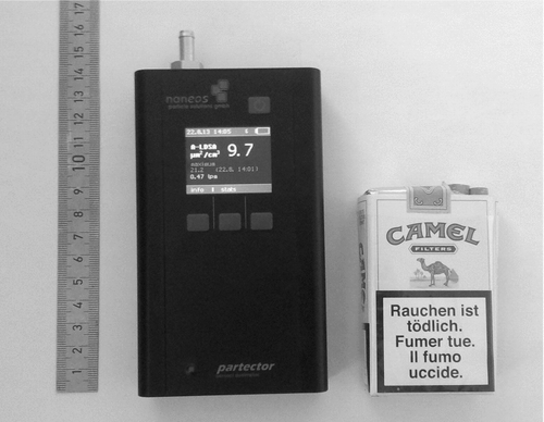
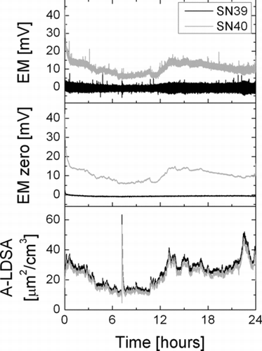
FIG. 6 Electrometer signals and computed LDSA for two partector instruments

FIG. 6 Electrometer signals and computed LDSA for two partector instruments

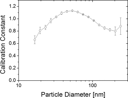
FIG. A1 A-LDSA calibration as function of particle size.

FIG. A1 A-LDSA calibration as function of particle size.

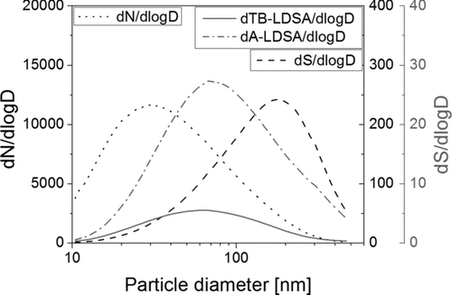
FIG. A2 Number- and surface-weighted particle size distributions in Zürich for 2008, and corresponding lung-deposited fractions.

FIG. A2 Number- and surface-weighted particle size distributions in Zürich for 2008, and corresponding lung-deposited fractions.

Reprints and Corporate Permissions

Please note: Selecting permissions does not provide access to the full text of the article, please see our help page How do I view content?

To request a reprint or corporate permissions for this article, please click on the relevant link below:

Academic Permissions

Please note: Selecting permissions does not provide access to the full text of the article, please see our help page How do I view content?

Obtain permissions instantly via Rightslink by clicking on the button below:

If you are unable to obtain permissions via Rightslink, please complete and submit this Permissions form. For more information, please visit our Permissions help page.