2,296
Views
72
CrossRef citations to date
0
Altmetric
Original Articles

Moderated, Water-Based, Condensational Particle Growth in a Laminar Flow

, &
Pages 401-408 | Received 06 Nov 2013, Accepted 24 Dec 2013, Published online: 24 Feb 2014

Figures & data

FIG. 1 Original and new, moderated approaches for laminar flow water condensation, with flow from left to right. With the original approach (top), flow from the conditioner enters a growth region with warm, wetted walls over its entire length. With the new, moderated approach (bottom) the flow from the conditioner enters a short, “initiator” section with warm wetted walls, followed by a cooler-walled “moderator” section. The overall length required is the same for both approaches.
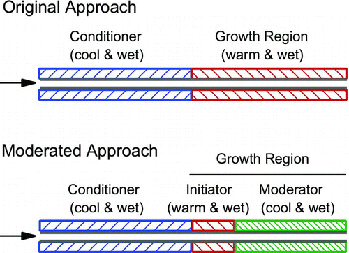
FIG. 1 Original and new, moderated approaches for laminar flow water condensation, with flow from left to right. With the original approach (top), flow from the conditioner enters a growth region with warm, wetted walls over its entire length. With the new, moderated approach (bottom) the flow from the conditioner enters a short, “initiator” section with warm wetted walls, followed by a cooler-walled “moderator” section. The overall length required is the same for both approaches.

FIG. 2 Saturation ratio calculated at the centerline of a laminar flow at 5°C and 95% RH entering a tube with wetted walls and various wall temperature profiles. In all cases the wall temperature ramps quickly from 5°C to 35°C. For the original configuration the walls stay at 35°C throughout the remaining length. For the new, moderated configuration the wall temperature is lowered after about 25% of the length to either 5°, 10°, or 20°. Plotted as a function of the axial distance from the entrance of the initiator, z, normalized by the characteristic length z 0 = Q/D (EquationEquation (1)).
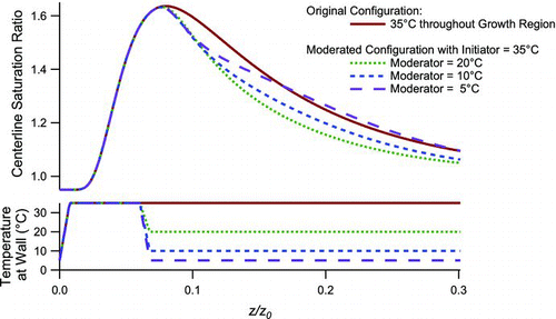
FIG. 2 Saturation ratio calculated at the centerline of a laminar flow at 5°C and 95% RH entering a tube with wetted walls and various wall temperature profiles. In all cases the wall temperature ramps quickly from 5°C to 35°C. For the original configuration the walls stay at 35°C throughout the remaining length. For the new, moderated configuration the wall temperature is lowered after about 25% of the length to either 5°, 10°, or 20°. Plotted as a function of the axial distance from the entrance of the initiator, z, normalized by the characteristic length z 0 = Q/D (EquationEquation (1)).

FIG. 3 Axial profiles of the (a) saturation ratio, (b) temperature, and (c) water vapor content in for a laminar flow in a tube at 5°C and 95% RH entering a growth region with 35°C wetted walls throughout (dashed lines, original approach) and for a growth region with a short “initiator” section at 35°C followed by a “moderator” section at 10°C. Profiles are shown along three trajectories at radial positions r = 0 (centerline), r = 0.50R o, and r = 0.75R o, where R o is the tube radius. The axial coordinate z is normalized with respect to the characteristic length z 0 = Q/D.
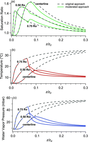
FIG. 3 Axial profiles of the (a) saturation ratio, (b) temperature, and (c) water vapor content in for a laminar flow in a tube at 5°C and 95% RH entering a growth region with 35°C wetted walls throughout (dashed lines, original approach) and for a growth region with a short “initiator” section at 35°C followed by a “moderator” section at 10°C. Profiles are shown along three trajectories at radial positions r = 0 (centerline), r = 0.50R o, and r = 0.75R o, where R o is the tube radius. The axial coordinate z is normalized with respect to the characteristic length z 0 = Q/D.

FIG. 4 Evolution of droplet diameter calculated for original approach with 5°C, 95% RH flow entering a wet walled tube at 35°C, and for the moderated approach of this article where the flow enters a 35°C inititiator followed by a 20°C moderator.
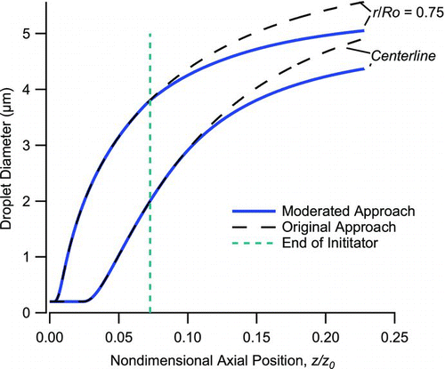
FIG. 4 Evolution of droplet diameter calculated for original approach with 5°C, 95% RH flow entering a wet walled tube at 35°C, and for the moderated approach of this article where the flow enters a 35°C inititiator followed by a 20°C moderator.

FIG. 5 Ratio of the peak supersaturation achieved with the initiator-moderator configuration to that from the original configuration, as a function of the initiator length zi , where z 0 = Q/D. Calculations are presented for cylindrical geometry at four sets of operating temperatures, where the entering temperature refers the entrance of the initiator or growth region (i.e., to that exiting the conditioner).
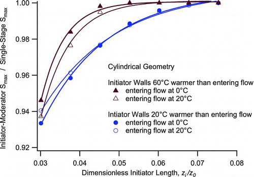
FIG. 5 Ratio of the peak supersaturation achieved with the initiator-moderator configuration to that from the original configuration, as a function of the initiator length zi , where z 0 = Q/D. Calculations are presented for cylindrical geometry at four sets of operating temperatures, where the entering temperature refers the entrance of the initiator or growth region (i.e., to that exiting the conditioner).

FIG. 6 Ratio of the peak supersaturation achieved with the initiator-moderator configuration to that from the original configuration, as a function of the initiator length z i , where z p 0 = qδ/D. Calculations are presented for parallel geometry, where the entering temperature refers the entrance of the initiator or growth region (i.e., that exiting the conditioner).
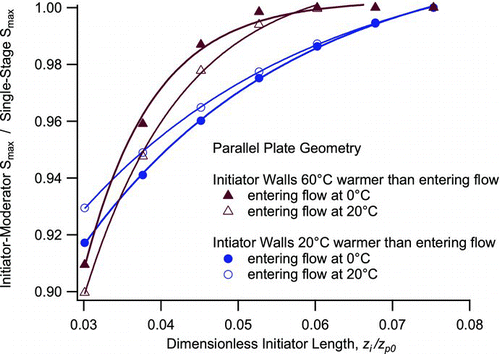
FIG. 6 Ratio of the peak supersaturation achieved with the initiator-moderator configuration to that from the original configuration, as a function of the initiator length z i , where z p 0 = qδ/D. Calculations are presented for parallel geometry, where the entering temperature refers the entrance of the initiator or growth region (i.e., that exiting the conditioner).
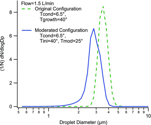
FIG. 7 Output droplet size distributions measured by an aerodynamic particle sizer for the original, warm-walled growth region and for the moderated approach of this article. Input is diluted ambient laboratory air.

FIG. 7 Output droplet size distributions measured by an aerodynamic particle sizer for the original, warm-walled growth region and for the moderated approach of this article. Input is diluted ambient laboratory air.

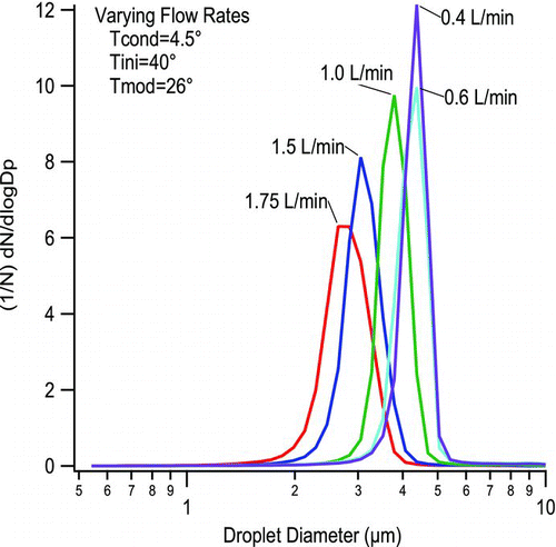
FIG. 8 Output droplet size distributions for the moderated approach at varying flow rates, with wall temperatures of 4.5°C, 40°C, and 26°C for the conditioner, initiator, and moderator, respectively. Input is diluted ambient laboratory air.

FIG. 8 Output droplet size distributions for the moderated approach at varying flow rates, with wall temperatures of 4.5°C, 40°C, and 26°C for the conditioner, initiator, and moderator, respectively. Input is diluted ambient laboratory air.

Reprints and Corporate Permissions

Please note: Selecting permissions does not provide access to the full text of the article, please see our help page How do I view content?

To request a reprint or corporate permissions for this article, please click on the relevant link below:

Academic Permissions

Please note: Selecting permissions does not provide access to the full text of the article, please see our help page How do I view content?

Obtain permissions instantly via Rightslink by clicking on the button below:

If you are unable to obtain permissions via Rightslink, please complete and submit this Permissions form. For more information, please visit our Permissions help page.