1,035
Views
29
CrossRef citations to date
0
Altmetric
Original Articles

Targeted Lung Delivery of Nasally Administered Aerosols

, &
Pages 434-449 | Received 15 Aug 2013, Accepted 07 Jan 2014, Published online: 24 Feb 2014

Figures & data

FIG. 1 Surface models of the interface device and conducting airway geometries including the (a) excipient enhanced growth (EEG) nasal cannula, (b) enhanced condensational growth (ECG) nasal cannula, (c) complete conducting airway model, and (d) expanded view of the stochastic individual path (SIP) model extending from the fourth bifurcation (B4) to the terminal bronchioles (B15) in the left lower (LL) lung lobe.
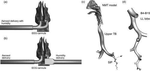
FIG. 1 Surface models of the interface device and conducting airway geometries including the (a) excipient enhanced growth (EEG) nasal cannula, (b) enhanced condensational growth (ECG) nasal cannula, (c) complete conducting airway model, and (d) expanded view of the stochastic individual path (SIP) model extending from the fourth bifurcation (B4) to the terminal bronchioles (B15) in the left lower (LL) lung lobe.

TABLE 1 Description of the four delivery cases implementing budesonide (BD) as a model insoluble drug and sodium chloride (NaCl) as an effective hygroscopic excipient

FIG. 2 RH contours on coronal planes in the nasal model and airway midplanes for delivery conditions described in in the NMT and upper TB model with (a) Case 1, (b) Cases 2 and 3, and (c) Case 4. RH values in the LL lobe SIP model are presented for (d) Case 1, (e) Cases 2 and 3, and (f) Case 4. For ECG Cases 2 and 3, the aerosol is delivered to the right nostril and humid air is delivered to the left nostril from the perspective of the subject.
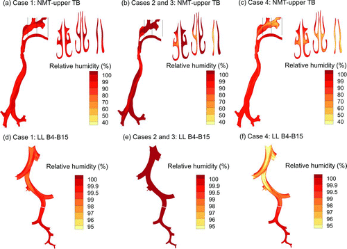
FIG. 2 RH contours on coronal planes in the nasal model and airway midplanes for delivery conditions described in Table 1 in the NMT and upper TB model with (a) Case 1, (b) Cases 2 and 3, and (c) Case 4. RH values in the LL lobe SIP model are presented for (d) Case 1, (e) Cases 2 and 3, and (f) Case 4. For ECG Cases 2 and 3, the aerosol is delivered to the right nostril and humid air is delivered to the left nostril from the perspective of the subject.

FIG. 3 Particle trajectories evaluated in the NMT and upper TB geometries contoured based on local geometric diameter for (a) Case 1: control, (b) Case 2: ECG with BD, (c) Case 3: ECG with BD:NaCl, and (d) Case 4: EEG with BD:NaCl. The calculated MMAD exiting B3 and entering the LL lobe is reported as well as a growth ratio (GR) calculated as MMADexit/(initial dgeo).
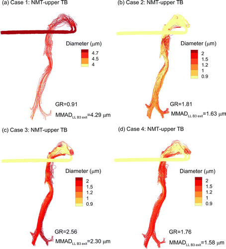
FIG. 3 Particle trajectories evaluated in the NMT and upper TB geometries contoured based on local geometric diameter for (a) Case 1: control, (b) Case 2: ECG with BD, (c) Case 3: ECG with BD:NaCl, and (d) Case 4: EEG with BD:NaCl. The calculated MMAD exiting B3 and entering the LL lobe is reported as well as a growth ratio (GR) calculated as MMADexit/(initial dgeo).

FIG. 4 Particle trajectories contoured based on local geometric diameter evaluated in the LL lobe SIP model extending from B4-B15 for (a) Case 1: control, (b) Case 2: ECG with BD, (c) Case 3: ECG with BD:NaCl, and (d) Case 4: EEG with BD:NaCl. The calculated MMAD exiting B15 and entering the alveolar region is reported as well as a growth ratio (GR) calculated as MMADexit/(initial dgeo).
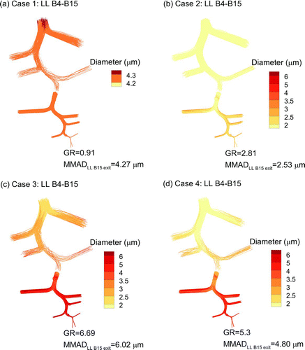
FIG. 4 Particle trajectories contoured based on local geometric diameter evaluated in the LL lobe SIP model extending from B4-B15 for (a) Case 1: control, (b) Case 2: ECG with BD, (c) Case 3: ECG with BD:NaCl, and (d) Case 4: EEG with BD:NaCl. The calculated MMAD exiting B15 and entering the alveolar region is reported as well as a growth ratio (GR) calculated as MMADexit/(initial dgeo).

TABLE 2 Mass median aerodynamic diameters (MMADs) exiting individual sections of the conducting airway model

TABLE 3 Deposition fraction (DF) as a percentage of initial delivered dose within individual regions of the respiratory airways. Comparisons to previously reported commercial products (Flovent MDI, Diskus DPI, Respimat, and Novolizer DPI) (Longest et al. Citation2012a,Citationc) with slow and deep (SD) and quick and deep (QD) inhalations are also included. Fraction remaining (FR) is the percentage of the initial dose that enters the alveolar region

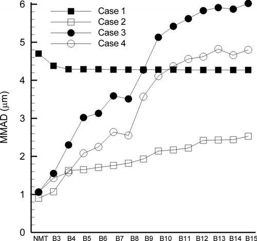
FIG. 5 MMAD of the aerosol as it enters the NMT region and each bifurcation from B3 to B15.

FIG. 5 MMAD of the aerosol as it enters the NMT region and each bifurcation from B3 to B15.

FIG. 6 Particle deposition locations and deposition fractions (DF) as percentages of the total delivered dose in the 20-cm delivery tube, cannula interface, NMT geometry, and upper TB region B1–B3. Contours represent the geometric diameter of the particle at the point of deposition.
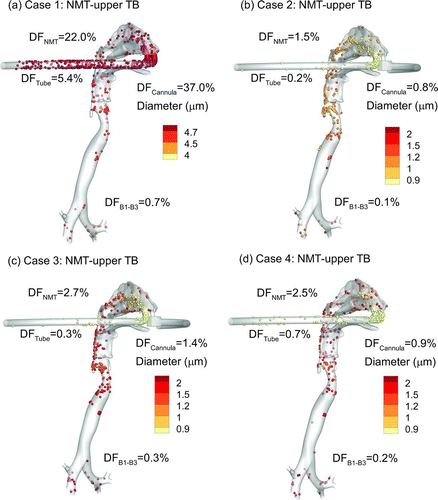
FIG. 6 Particle deposition locations and deposition fractions (DF) as percentages of the total delivered dose in the 20-cm delivery tube, cannula interface, NMT geometry, and upper TB region B1–B3. Contours represent the geometric diameter of the particle at the point of deposition.

FIG. 7 Particle deposition locations and deposition fractions as percentages of the total delivered dose in the LL lobe SIP model. Contours represent the geometric diameter of the particle at the point of deposition.
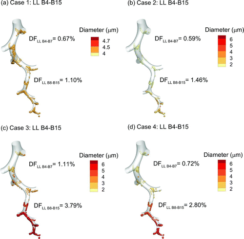
FIG. 7 Particle deposition locations and deposition fractions as percentages of the total delivered dose in the LL lobe SIP model. Contours represent the geometric diameter of the particle at the point of deposition.

FIG. 8 Comparison of deposition fractions in individual regions of the conducting airways for Cases 1–4.
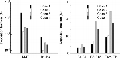
FIG. 8 Comparison of deposition fractions in individual regions of the conducting airways for Cases 1–4.

FIG. 9 Comparison of deposition fractions in the lower TB airways for nose-to-lung delivery with predictions of oral inhalation delivery from commercial inhalers (Longest et al. Citation2012a,Citationc).
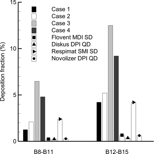
FIG. 9 Comparison of deposition fractions in the lower TB airways for nose-to-lung delivery with predictions of oral inhalation delivery from commercial inhalers (Longest et al. Citation2012a,Citationc).
Supplemental material

Supplimental_files_for_publication.zip

Download Zip (17.7 KB)

Reprints and Corporate Permissions

Please note: Selecting permissions does not provide access to the full text of the article, please see our help page How do I view content?

To request a reprint or corporate permissions for this article, please click on the relevant link below:

Academic Permissions

Please note: Selecting permissions does not provide access to the full text of the article, please see our help page How do I view content?

Obtain permissions instantly via Rightslink by clicking on the button below:

If you are unable to obtain permissions via Rightslink, please complete and submit this Permissions form. For more information, please visit our Permissions help page.