755
Views
5
CrossRef citations to date
0
Altmetric
Original Articles

Computational Analysis of Particle Nucleation in Dilution Tunnels: Effects of Flow Configuration and Tunnel Geometry

, , , , &
Pages 638-648 | Received 11 Oct 2013, Accepted 24 Feb 2014, Published online: 19 May 2014

Figures & data

TABLE 1 Flow parameters and boundary conditions for the cross-flow and axial flow tunnels for dilution ratios of 20 and 110
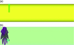
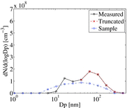
FIG. 1. Geometries of (a) the cross-flow and (b) axial-flow tunnels. Only regions of the tunnels near the sample inlet are shown. For reference, the diameters of the cross-flow and axial-flow tunnels are 0.15 m and 0.11 m, respectively.
FIG. 2. Measured (solid line), truncated (dashed line), and sample (dash-dot line) particle number distributions (PND) for the cross-flow tunnel at DR = 110.
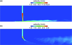
FIG. 3. Contours of instantaneous velocity magnitude on a cross-section through the center of the cross-flow tunnel for (a) DR = 20 and (b) DR = 110.
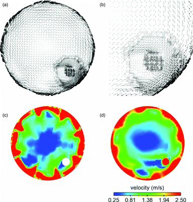
FIG. 4. Instantaneous velocity vectors on a cross-section (a) near the sample inlet (b) in a small region near the sample inlet, and contours of instantaneous velocity magnitude (c) immediately downstream of the swirler (d) near the sample inlet for the axial-flow tunnel at DR = 20.
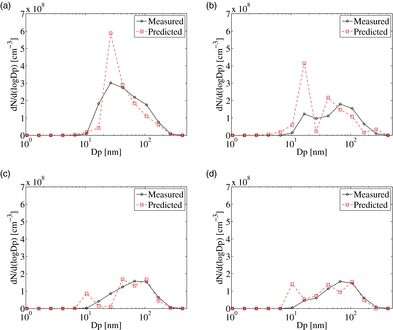
FIG. 5. Measured (solid line) and predicted (dashed line) PND at the tunnel exits for the cross-flow tunnel at (a) DR = 20, (b) DR = 110, and the axial-flow tunnel at (c) DR = 20, (d) DR = 110.
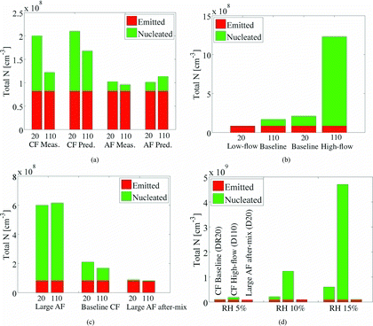
FIG. 6. (a) Comparison of the measured and predicted total N at the tunnel exits for the cross-flow (CF) and the axial-flow (AF) tunnels at DR 20 and 110, (b) model predictions of total N at the tunnel exit for DR 20 low-flow, DR 110 baseline, DR 20 baseline, and DR 110 high-flow cases of the cross-flow (CF) tunnel, (c) model predictions of total N at tunnel exits for large axial-flow (AF) tunnel, baseline cross-flow (CF) tunnel, and large axial-flow (AF) tunnel with after-mixing, and (d) model predictions of total N at the tunnel exits for DR 20 baseline and DR 110 high-flow cases of the cross-flow (CF) tunnel, and for DR 20 of large axial-flow (AF) tunnel with after-mixing for dilution air relative humidity (RH) of 5%, 10%, and 15%.
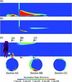
FIG. 7. Contours of instantaneous nucleation rate in the tunnels for cross-flow tunnel at (a) DR = 20, (b) DR = 110, and (c) the axial-flow tunnel at DR = 20.
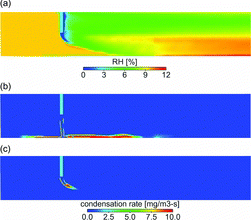
FIG. 8. Contours of instantaneous RH on a cross-section in the center of the cross-flow tunnel at DR = 110, (b) contours of instantaneous H2SO4 condensation rate at DR = 20, and (c) contours of instantaneous H2SO4 condensation rate at DR = 110.
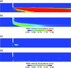
FIG. 9. (a) Contours of instantaneous nucleation rate, (b) contours of root-mean-squared (RMS) velocity fluctuations for DR = 110 high-flow case, (c) contours of instantaneous nucleation rate, and (d) contours of RMS velocity fluctuations for DR = 20 flow-flow case of the cross-flow tunnel. Legend for nucleation rate is provided in Figure 7.
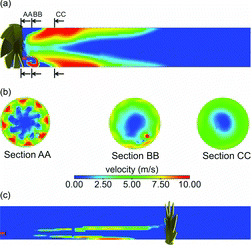
FIG. 10. Contours of (a) instantaneous nucleation rate (b) instantaneous velocity magnitude for DR = 20 of large axial-flow tunnel, and (c) contours of instantaneous nucleation rate for DR = 20 of the large axial-flow (AF) tunnel with after-mixing. Legend for nucleation rate is provided in Figure 7.
Supplemental material

JAST_2013_Supplemental.zip

Download Zip (318.9 KB)

Reprints and Corporate Permissions

Please note: Selecting permissions does not provide access to the full text of the article, please see our help page How do I view content?

To request a reprint or corporate permissions for this article, please click on the relevant link below:

Academic Permissions

Please note: Selecting permissions does not provide access to the full text of the article, please see our help page How do I view content?

Obtain permissions instantly via Rightslink by clicking on the button below:

If you are unable to obtain permissions via Rightslink, please complete and submit this Permissions form. For more information, please visit our Permissions help page.