1,968
Views
84
CrossRef citations to date
0
Altmetric
Original Articles

Ns-Soot: A Material-Based Term for Strongly Light-Absorbing Carbonaceous Particles

, , , &
Pages 777-788 | Received 22 Nov 2013, Accepted 12 Apr 2014, Published online: 25 Jun 2014

Figures & data

TABLE 1 Methods for measuring the concentrations or properties of ns-soot and BC

FIG. 1. TEM images of ns-soot and carbon nanospheres. (a) An ns-soot particle from NIST Standard Reference Material (SRM) 1650b (diesel particulate matter). Scale bar = 200 nm. The inset shows a schematic image of carbonaceous nanospheres aggregated to form ns-soot. (b) Enlarged image of (a). Scale bar = 20 nm. (c) High-resolution image of ns-soot particle from (b). The lattice fringes of the ns-soot are evident. Scale bar = 5 nm.

FIG. 1. TEM images of ns-soot and carbon nanospheres. (a) An ns-soot particle from NIST Standard Reference Material (SRM) 1650b (diesel particulate matter). Scale bar = 200 nm. The inset shows a schematic image of carbonaceous nanospheres aggregated to form ns-soot. (b) Enlarged image of (a). Scale bar = 20 nm. (c) High-resolution image of ns-soot particle from (b). The lattice fringes of the ns-soot are evident. Scale bar = 5 nm.

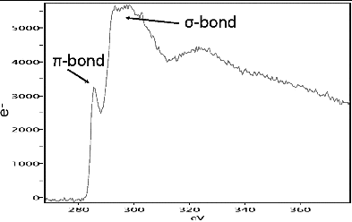
FIG. 2. EELS of ns-soot from Mexico City showing peaks arising from carbon π- and σ-bonding.

FIG. 2. EELS of ns-soot from Mexico City showing peaks arising from carbon π- and σ-bonding.

FIG. 3. (a) Typical SAED pattern of ns-soot from the emission of diesel engines from three buses that correspond to European Emission Standards Euro0, 3, and 4 (http://en.wikipedia.org/wiki/European_emission_standards). The rings correspond to lattice spacings of (1) ∼0.36, (2) 0.205, and (3) 0.12 nm. (b) Spacings measured in SAED patterns obtained from ns-soot particles (each column in the diagram refers to a distinct particle). The d-value shown for each particle corresponds to the second ring in their SAED patterns (numbered 2 in (a)). The circles above the columns represent the typical diameters of the carbon nanospheres that constitute the ns-soot particles: small (∼20 to 30 nm), medium (∼30 to 50), and large (>50 nm). Two lattice spacings for graphite are also shown by the horizontal lines. They refer to (010) (upper) and (011) graphite spacings, respectively; the measured spacings cluster around the graphite (011) value. No relationship is apparent between measured spacings and the sizes of constituent carbon nanospheres or the make and year of the buses.
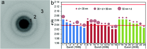
FIG. 3. (a) Typical SAED pattern of ns-soot from the emission of diesel engines from three buses that correspond to European Emission Standards Euro0, 3, and 4 (http://en.wikipedia.org/wiki/European_emission_standards). The rings correspond to lattice spacings of (1) ∼0.36, (2) 0.205, and (3) 0.12 nm. (b) Spacings measured in SAED patterns obtained from ns-soot particles (each column in the diagram refers to a distinct particle). The d-value shown for each particle corresponds to the second ring in their SAED patterns (numbered 2 in (a)). The circles above the columns represent the typical diameters of the carbon nanospheres that constitute the ns-soot particles: small (∼20 to 30 nm), medium (∼30 to 50), and large (>50 nm). Two lattice spacings for graphite are also shown by the horizontal lines. They refer to (010) (upper) and (011) graphite spacings, respectively; the measured spacings cluster around the graphite (011) value. No relationship is apparent between measured spacings and the sizes of constituent carbon nanospheres or the make and year of the buses.

FIG. 4. TEM images of internally mixed ns-soot particles from Mexico showing (a), (b) coating, and (c) embedding, although (b) shows that the distinction is gradational. The ribbon-like features are from the lacey-carbon substrate. Samples (a) and (b) were collected from Mexico City and (c) was collected from biomass burning in Mexico. All samples were collected during the MILAGRO campaign (Adachi and Buseck Citation2008).
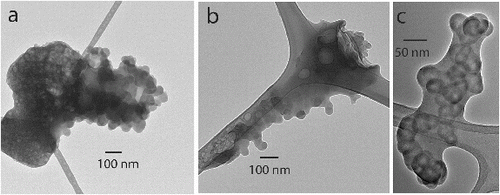
FIG. 4. TEM images of internally mixed ns-soot particles from Mexico showing (a), (b) coating, and (c) embedding, although (b) shows that the distinction is gradational. The ribbon-like features are from the lacey-carbon substrate. Samples (a) and (b) were collected from Mexico City and (c) was collected from biomass burning in Mexico. All samples were collected during the MILAGRO campaign (Adachi and Buseck Citation2008).

FIG. 5. Schematic images of (left) ns-soot, (center) internally mixed ns-soot particle, and (right) an ensemble of particles, the total absorption of which would be referred to as from BC when measured with an aethalometer. The aggregated, black layered spherules indicate ns-soot, are evident as faint spherules within the large particle in the center part.
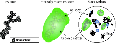
FIG. 5. Schematic images of (left) ns-soot, (center) internally mixed ns-soot particle, and (right) an ensemble of particles, the total absorption of which would be referred to as from BC when measured with an aethalometer. The aggregated, black layered spherules indicate ns-soot, are evident as faint spherules within the large particle in the center part.

FIG. 6. High-resolution TEM images of (a) bare and (b) coated ns-soot particles from diesel emissions from buses. The arrows in (b) indicate an amorphous coating on carbon nanospheres.
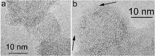
FIG. 6. High-resolution TEM images of (a) bare and (b) coated ns-soot particles from diesel emissions from buses. The arrows in (b) indicate an amorphous coating on carbon nanospheres.

FIG. 7. Atomic force microscope images of (a) bare, (b) partly coated, and (c) embedded soot particles, all collected from the emissions of vehicles with internal combustion engines.
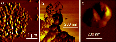
FIG. 7. Atomic force microscope images of (a) bare, (b) partly coated, and (c) embedded soot particles, all collected from the emissions of vehicles with internal combustion engines.

FIG. 8. (a) Part of Figure 5b, with the contrast of graphene-like layers in ns-soot enhanced digitally. (b) A schematic model for three layers. They are graphene-like, but some C atoms are missing from the hexagonal nets. The missing atoms break the periodic order and presumably cause the misalignment of layer segments relative to one another, resulting in the layer curvature. H in ns-soot can be accommodated around the sites of missing C atoms, where some C atoms can be bonded to two C and one H.
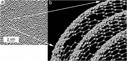
FIG. 8. (a) Part of Figure 5b, with the contrast of graphene-like layers in ns-soot enhanced digitally. (b) A schematic model for three layers. They are graphene-like, but some C atoms are missing from the hexagonal nets. The missing atoms break the periodic order and presumably cause the misalignment of layer segments relative to one another, resulting in the layer curvature. H in ns-soot can be accommodated around the sites of missing C atoms, where some C atoms can be bonded to two C and one H.
Reprints and Corporate Permissions

Please note: Selecting permissions does not provide access to the full text of the article, please see our help page How do I view content?

To request a reprint or corporate permissions for this article, please click on the relevant link below:

Academic Permissions

Please note: Selecting permissions does not provide access to the full text of the article, please see our help page How do I view content?

Obtain permissions instantly via Rightslink by clicking on the button below:

If you are unable to obtain permissions via Rightslink, please complete and submit this Permissions form. For more information, please visit our Permissions help page.