Figures & data
FIG. 1. Profiles of in fully developed turbulent flow for particle response times τ+p = 0.2, 1, 5, and 25, from the turbulent channel-flow simulations of Picciotto et al. (Citation2005) at Reτ = 150.
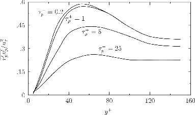
FIG. 2. Profiles of in the near-wall region of fully developed turbulent flow for particle response times τ+p = 0, 2.5, 5, and 10, calculated as solutions to Equation (Equation8
[8] ), with Equation (Equation9
[9] ) as the initial condition.
![FIG. 2. Profiles of in the near-wall region of fully developed turbulent flow for particle response times τ+p = 0, 2.5, 5, and 10, calculated as solutions to Equation (Equation8[8] ), with Equation (Equation9[9] ) as the initial condition.](/cms/asset/f84c9f11-edaa-4f9e-8e9c-4e547f54c265/uast_a_1073847_f0002_b.gif)
FIG. 3. Turbophoretic particle deposition velocity V+dep in turbulent channel flow, as a function of the particle relaxation timescale τ+p, for the model predictions of Equation (Equation16[16] ) and the experimental data of Liu and Agarwal (Citation1974): × at Re = 10, 000 and + at Re = 50, 000.
![FIG. 3. Turbophoretic particle deposition velocity V+dep in turbulent channel flow, as a function of the particle relaxation timescale τ+p, for the model predictions of Equation (Equation16[16] ) and the experimental data of Liu and Agarwal (Citation1974): × at Re = 10, 000 and + at Re = 50, 000.](/cms/asset/690f10a3-a9f8-4340-9305-296d4110300f/uast_a_1073847_f0003_b.gif)
FIG. 4. (a) The particle mass flux boundary condition applied at the pipe surface. (b) The mixed-mean temperature as a function of cooling-section inlet temperature Tin in the heated pipe-flow experiments of Romay et al. (Citation1998).
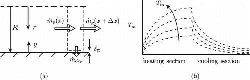
FIG. 5. Deposition efficiency η of NaCl particles as a function of cooling-section inlet temperature Tin in laminar pipe flow at Re = 1397. Solid lines describe model predictions and symbols denote the experimental data of Romay et al. (Citation1998).
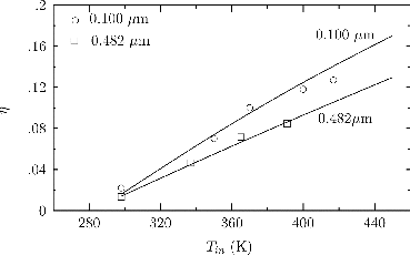
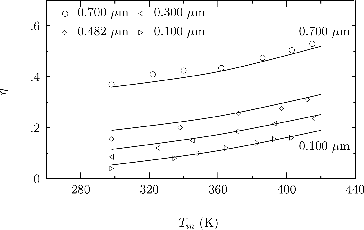
FIG. 6. Deposition efficiency η of NaCl particles as a function of cooling-section inlet temperature Tin in pipe flow at Re = 5517. Solid lines describe model predictions and symbols denote the experimental data of Romay et al. (Citation1998).
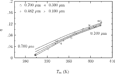
FIG. 7. Deposition efficiency η of NaCl particles as a function of cooling-section inlet temperature Tin in pipe flow at Re = 9656. Solid lines describe model predictions and symbols denote the experimental data of Romay et al. (Citation1998).