1,083
Views
11
CrossRef citations to date
0
Altmetric
Articles

Experimental investigation of jet-induced resuspension of indoor deposited particles

, &
Pages 230-241 | Received 19 Oct 2015, Accepted 05 Jan 2016, Published online: 18 Feb 2016

Figures & data

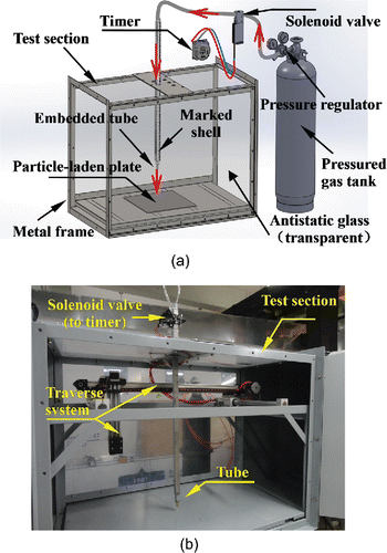
Figure 1. The jet generation device in the test section: (a) schematics, and (b) picture.

Figure 1. The jet generation device in the test section: (a) schematics, and (b) picture.

Table 1. Measured roughness of particle-deposited plate surfaces.

Figure 2. Pictures of the deposited dusts on the rough stainless steel plates photographed by a 3D super depth digital microscope in which the dark dots represent particles.
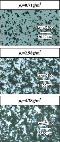
Figure 2. Pictures of the deposited dusts on the rough stainless steel plates photographed by a 3D super depth digital microscope in which the dark dots represent particles.

Table 2. Major parameters of the experiments.

Figure 3. Jet-induced dust cloud from a rough stainless steel plate with H/D = 5 and ρs = 4.78 g/m2.
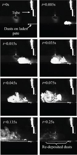
Figure 3. Jet-induced dust cloud from a rough stainless steel plate with H/D = 5 and ρs = 4.78 g/m2.

Figure 4. Pictures of the rough stainless steel plates with deposited dusts (ρs = 4.78 g/m2, upper parts) and the normalized light intensity along the horizontal central lines (lower parts) after a jet impingement at different heights: (a) H/D = 5, and (b) H/D = 20.
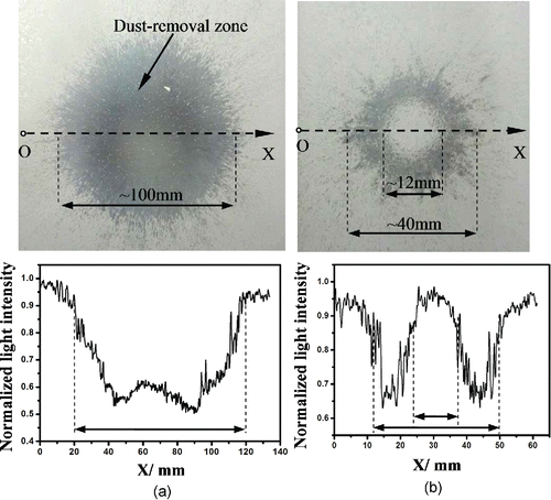
Figure 4. Pictures of the rough stainless steel plates with deposited dusts (ρs = 4.78 g/m2, upper parts) and the normalized light intensity along the horizontal central lines (lower parts) after a jet impingement at different heights: (a) H/D = 5, and (b) H/D = 20.

Figure 5. Impingement jet plume and the generated wall shear stress: (a) a half-sectional view of a circular jet contour and the shear stress distribution, (b) variation of τ/τmax with the horizontal distance from the stagnation point, and (c) variation of normalized τmax with the jet height.
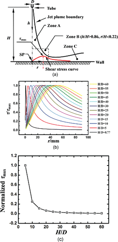
Figure 5. Impingement jet plume and the generated wall shear stress: (a) a half-sectional view of a circular jet contour and the shear stress distribution, (b) variation of τ/τmax with the horizontal distance from the stagnation point, and (c) variation of normalized τmax with the jet height.

Figure 6. Variation of the dust-removal mass from a rough stainless steel plate with the jet impingement height: (a) with ρs = 1.44 g/m2, removal mass normalized by 0.00339 g, and (b) with ρs = 4.78 g/m2, normalized by 0.02169 g.
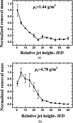
Figure 6. Variation of the dust-removal mass from a rough stainless steel plate with the jet impingement height: (a) with ρs = 1.44 g/m2, removal mass normalized by 0.00339 g, and (b) with ρs = 4.78 g/m2, normalized by 0.02169 g.

Figure 7. Variation of the total airborne particle numbers resuspended from the rough stainless steel plate with the jet impingement height; particles within the bin size of 1 to 3 μm refer to the left coordinate and other bin sizes to the right coordinate: (a) ρs = 1.44 g/m2, and (b) ρs = 4.78 g/m2.
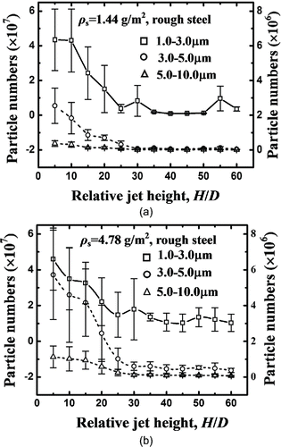
Figure 7. Variation of the total airborne particle numbers resuspended from the rough stainless steel plate with the jet impingement height; particles within the bin size of 1 to 3 μm refer to the left coordinate and other bin sizes to the right coordinate: (a) ρs = 1.44 g/m2, and (b) ρs = 4.78 g/m2.

Figure 8. Variation of the particle resuspension with the surface dust load after a jet impingement at H/D = 20: (a) dust-removal mass normalized by 0.01551 g, and (b) airborne particle numbers; particles within a bin size of 1 to 3 μm refer to the left coordinate and other bin sizes to the right coordinate.
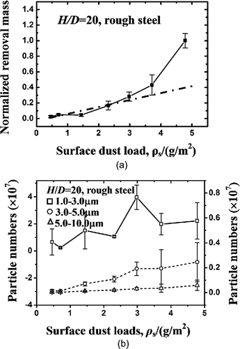
Figure 8. Variation of the particle resuspension with the surface dust load after a jet impingement at H/D = 20: (a) dust-removal mass normalized by 0.01551 g, and (b) airborne particle numbers; particles within a bin size of 1 to 3 μm refer to the left coordinate and other bin sizes to the right coordinate.

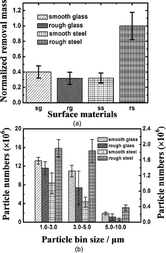
Figure 9. Particle resuspension from different material surfaces: (a) dust-removal mass normalized by 0.00106 g, and (b) particle numbers; left coordinate for a bin size of 1 to 3 μm and right coordinate for other bin sizes.

Figure 9. Particle resuspension from different material surfaces: (a) dust-removal mass normalized by 0.00106 g, and (b) particle numbers; left coordinate for a bin size of 1 to 3 μm and right coordinate for other bin sizes.

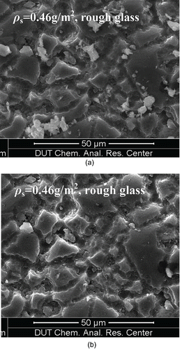
Figure 10. Deposited dusts on the rough glass plate: (a) before a jet impingement, and (b) after a jet impingement.

Figure 10. Deposited dusts on the rough glass plate: (a) before a jet impingement, and (b) after a jet impingement.
Supplemental material

UAST_1143084_Supplementary_Files.zip

Download Zip (4.3 MB)

Reprints and Corporate Permissions

Please note: Selecting permissions does not provide access to the full text of the article, please see our help page How do I view content?

To request a reprint or corporate permissions for this article, please click on the relevant link below:

Academic Permissions

Please note: Selecting permissions does not provide access to the full text of the article, please see our help page How do I view content?

Obtain permissions instantly via Rightslink by clicking on the button below:

If you are unable to obtain permissions via Rightslink, please complete and submit this Permissions form. For more information, please visit our Permissions help page.