755
Views
0
CrossRef citations to date
0
Altmetric
Articles

Monte Carlo N-particle tracking of ultrafine particle flow in bent microtubes

&
Pages 272-283 | Received 05 Oct 2015, Accepted 01 Jan 2016, Published online: 26 Feb 2016

Figures & data

Figure 1. Important parameters defining toroidal flow system geometries.

Figure 1. Important parameters defining toroidal flow system geometries.

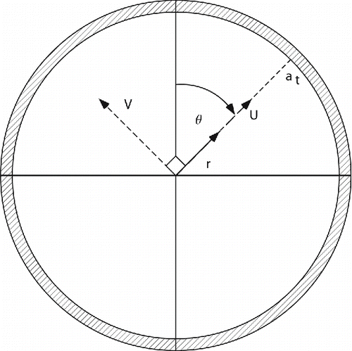
Figure 2. Definition of secondary flow velocity parameters.

Figure 2. Definition of secondary flow velocity parameters.

Table 1. Model parameter space.

Figure 3. Display of the secondary streamlines as defined by EquationEquations (12) and Equation(13).

Figure 3. Display of the secondary streamlines as defined by EquationEquations (12)[12] and Equation(13)[13] .

Figure 4. Axial streamlines (contour lines represent equal axial velocity) for top: a straight tube (K = 0) and for bottom: a bent tube (K = 400). In both cases, W0 has been normalized to 1.
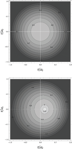
Figure 4. Axial streamlines (contour lines represent equal axial velocity) for top: a straight tube (K = 0) and for bottom: a bent tube (K = 400). In both cases, W0 has been normalized to 1.

Figure 5. Transmission fractions for at = 25 µm and P0 = 1.87 atmospheres as a function of Rb and T. Each point is the mean of 10 calculations and the error bars represent one standard deviation from the mean of those same 10 calculations.

Figure 5. Transmission fractions for at = 25 µm and P0 = 1.87 atmospheres as a function of Rb and T. Each point is the mean of 10 calculations and the error bars represent one standard deviation from the mean of those same 10 calculations.

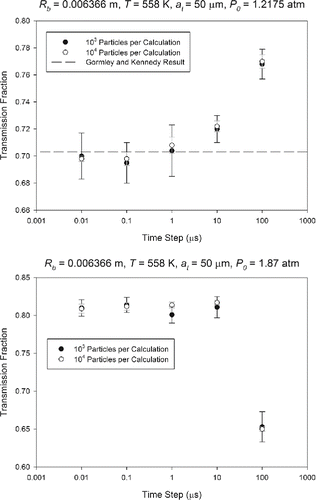
Figure 6. Selected results from remaining tests sets for illustration.

Figure 6. Selected results from remaining tests sets for illustration.

Figure 7. Deposition patterns for the system with parameters at = 25 µm, P0 = 1.87 atm, T = 558 K, time step = 0.01 µs.
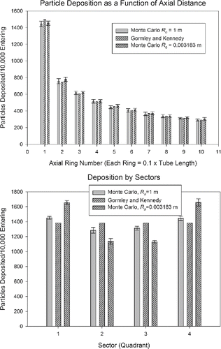
Figure 7. Deposition patterns for the system with parameters at = 25 µm, P0 = 1.87 atm, T = 558 K, time step = 0.01 µs.

Figure 8. Deposition patterns for the system with parameters at = 50 µm, P0 = 1.2175 atm, T = 298 K, time step = 0.01 µs.
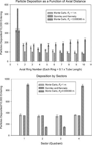
Figure 8. Deposition patterns for the system with parameters at = 50 µm, P0 = 1.2175 atm, T = 298 K, time step = 0.01 µs.

Table 2. Comparison of parameters of interest in EquationEquations (25)Equation(28), T = 558 K. In all cases, dp = 10 nm, ρp = 1 g/cm3.

Supplemental material

UAST_1143548_Supplementary_File.zip

Download Zip (5.7 MB)

Reprints and Corporate Permissions

Please note: Selecting permissions does not provide access to the full text of the article, please see our help page How do I view content?

To request a reprint or corporate permissions for this article, please click on the relevant link below:

Academic Permissions

Please note: Selecting permissions does not provide access to the full text of the article, please see our help page How do I view content?

Obtain permissions instantly via Rightslink by clicking on the button below:

If you are unable to obtain permissions via Rightslink, please complete and submit this Permissions form. For more information, please visit our Permissions help page.