1,770
Views
16
CrossRef citations to date
0
Altmetric
Articles

Development of a volatility and polarity separator (VAPS) for volatility- and polarity-resolved organic aerosol measurement

, , , , , , , , & show all
Pages 255-271 | Received 20 Sep 2015, Accepted 12 Jan 2016, Published online: 26 Feb 2016

Figures & data

Figure 1. (a) Schematic of the VAPS modulator system. The heat exchanger provides a constant 0.5 cfm hot air flow to the modulator. A 2.5 cfm cold air flow is switched on during the trapping phase and off during the heating phase. (b) Chromatogram showing polarity resolution of three compounds of similar volatility and differing polarity. (c) 2D vapogram plot of same sample. Polarity units are shown as number of mass spectra acquired since start of modulator hot pulse, and the volatility axis bins are reversed from acquisition order to present with increasing volatility in moving from left to right.
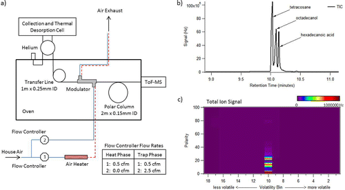
Figure 1. (a) Schematic of the VAPS modulator system. The heat exchanger provides a constant 0.5 cfm hot air flow to the modulator. A 2.5 cfm cold air flow is switched on during the trapping phase and off during the heating phase. (b) Chromatogram showing polarity resolution of three compounds of similar volatility and differing polarity. (c) 2D vapogram plot of same sample. Polarity units are shown as number of mass spectra acquired since start of modulator hot pulse, and the volatility axis bins are reversed from acquisition order to present with increasing volatility in moving from left to right.

Figure 2. Results from testing transfer line materials. Each chemical class is comprised of 3 compounds covering a range of volatilities (see text for details). The z-axis displays materials tested for overall transfer. In the left bracket is a 30 m low-polar column typically used for traditional GC. The center bracket contains fixed length (35 cm, 0.25 mm ID) sections of transfer-line materials used to deliver sample between the CTD cell, through the modulator, and onto the polar column. Finally, the right bracket contains two polar column materials tested. All signals have been normalized to the response of the 30 m column.
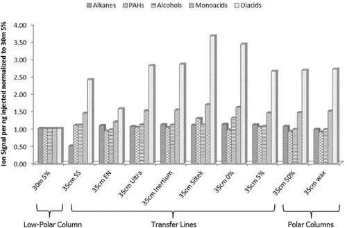
Figure 2. Results from testing transfer line materials. Each chemical class is comprised of 3 compounds covering a range of volatilities (see text for details). The z-axis displays materials tested for overall transfer. In the left bracket is a 30 m low-polar column typically used for traditional GC. The center bracket contains fixed length (35 cm, 0.25 mm ID) sections of transfer-line materials used to deliver sample between the CTD cell, through the modulator, and onto the polar column. Finally, the right bracket contains two polar column materials tested. All signals have been normalized to the response of the 30 m column.

Figure 3. (a) Transfer of an even alkane standard without the modulator. (b) Transfer of an even alkane standard with the modulator (18 bins) showing good separation and over 20 times more signal. Plotted in solid lines are MS signal at m/z 57 and temperature of oven ramp. Temperature of hot air flow and temperature of modulator are plotted in dashed lines.
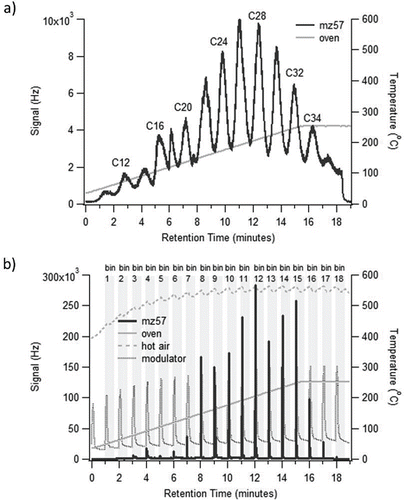
Figure 3. (a) Transfer of an even alkane standard without the modulator. (b) Transfer of an even alkane standard with the modulator (18 bins) showing good separation and over 20 times more signal. Plotted in solid lines are MS signal at m/z 57 and temperature of oven ramp. Temperature of hot air flow and temperature of modulator are plotted in dashed lines.

Figure 4. Example 2D vapogram plot of an ambient sample (collected in Brent, AL) with 18 volatility bins on the x-axis and polarity on the y-axis. (a) Total ion signal, (b) m/z 55 ion signal, (c) C4H7+ high-resolution ion signal, and (d) C3H3O+ high-resolution ion signal.
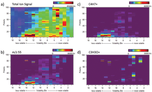
Figure 4. Example 2D vapogram plot of an ambient sample (collected in Brent, AL) with 18 volatility bins on the x-axis and polarity on the y-axis. (a) Total ion signal, (b) m/z 55 ion signal, (c) C4H7+ high-resolution ion signal, and (d) C3H3O+ high-resolution ion signal.

Table 1. Compounds in standard for testing of system performance.

Figure 5. (a) Example vapogram of a sample from an urban site in St. Louis, MO. (b) Example vapogram of a sample from a rural site in Brent, AL. Numbered labels refer to individual resolved species described in Table S3.
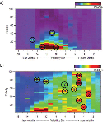
Figure 5. (a) Example vapogram of a sample from an urban site in St. Louis, MO. (b) Example vapogram of a sample from a rural site in Brent, AL. Numbered labels refer to individual resolved species described in Table S3.
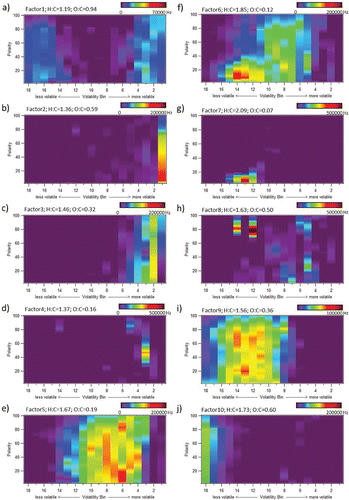
Figure 6. Vapogram of each factor for a 10-factor PMF analysis of data recorded by VAPS during the period 16–19 June 2013 during SOAS in Brent, AL. Also shown are H:C and O:C ratios for each factor from elemental analysis of high resolution ions.

Figure 6. Vapogram of each factor for a 10-factor PMF analysis of data recorded by VAPS during the period 16–19 June 2013 during SOAS in Brent, AL. Also shown are H:C and O:C ratios for each factor from elemental analysis of high resolution ions.

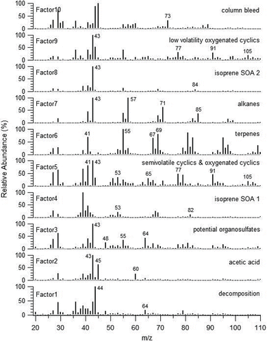
Figure 7. Average mass spectrum of each factor for the 10-factor PMF analysis. Each factor is identified on the basis of location of signal intensity in vapogram, major ions present in mass spectrum, and mass spectral match to NIST database.

Figure 7. Average mass spectrum of each factor for the 10-factor PMF analysis. Each factor is identified on the basis of location of signal intensity in vapogram, major ions present in mass spectrum, and mass spectral match to NIST database.
Supplemental material

UAST_1147645_Supplementary_File.zip

Download Zip (773 KB)

Reprints and Corporate Permissions

Please note: Selecting permissions does not provide access to the full text of the article, please see our help page How do I view content?

To request a reprint or corporate permissions for this article, please click on the relevant link below:

Academic Permissions

Please note: Selecting permissions does not provide access to the full text of the article, please see our help page How do I view content?

Obtain permissions instantly via Rightslink by clicking on the button below:

If you are unable to obtain permissions via Rightslink, please complete and submit this Permissions form. For more information, please visit our Permissions help page.