Figures & data
Table 1. List of commercially available portable aerosol sizers (based on particle electric mobility technique).
Figure 1. Schematic diagram of studied mini-plate DMA: (a) the sectional view and (b) the top view.
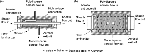
Table 2. Key dimensions of two studied mini-plate DMAs, units: inch (mm).
Figure 2. Experimental setup for the performance evaluation of mini-plate DMAs.
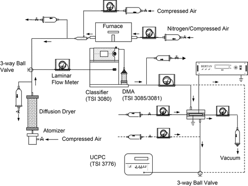
Figure 3. Comparison of central voltage for particle sizing among experimental data, calculated data with and without correction: (a) for DMA-1 and (b) for DMA-2.
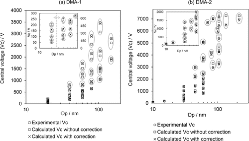
Figure 4. Correction factor, η, as a function of aerosol-to-sheath flow rate ratio, β, for studied mini-plate DMAs.
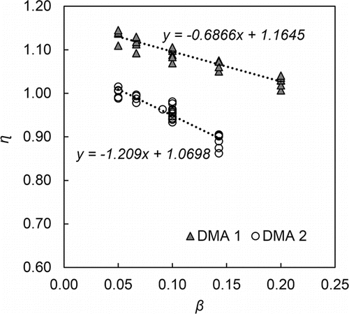
Figure 5. (a) Comparison of experimental and calculated TDMA curves for DMA-1 and DMA-2; (b) typical transfer functions of DMA-1 and DMA-2 for 100 nm particle size, obtained via the linear-piecewise function deconvolution scheme, when operated at the aerosol-to-sheath flow rate ratio of 0.1.
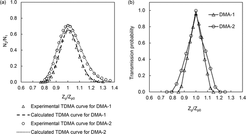
Figure 6. Comparison of the area (a), height (b), and FWHM (c) of the transfer function for mini-plate DMA-1 at various operational flow conditions. Also included in the figure are the experimental transfer function data of PAMS DMA presented in AAAR 2011 (Qi et al. Citation2011).
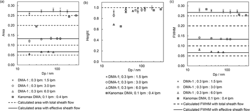
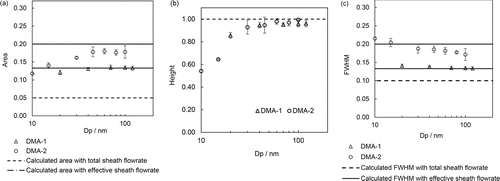
Figure 7. Comparison of area (a), height (b), and FWHM (c) of mini-plate DMA-2 and DMA-2 at the aerosol and sheath flow rate of 0.3 and 3.0 lpm, respectively.