Figures & data
Figure 1. Mean particle size distributions obtained at the Downtown Los Angeles site for stable presunrise hours at various downwind locations from the freeway plume peak: Black solid line is size distribution at the peak location; dashed (blue) line at 300 m downwind from the peak; grey solid (green) at 500 m downwind; dash-dotted (orange) at 1 km downwind; and grey dotted line for the upwind background. Black dashed (brown) rectangles represent selected size-bins for the present study (see text for the details of selected size-bins).
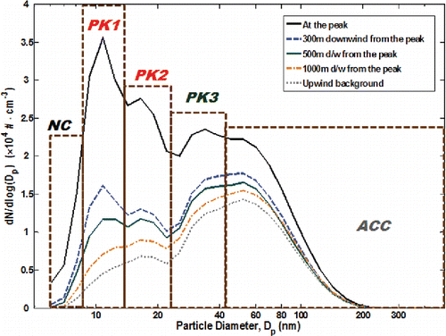
Figure 2. Background subtracted particle number concentration (PNC, Δ[N]) profiles with distance from the center of freeway for each size bin. Symbols represent observation values and dotted lines show the fitting results using the modified GB model.
![Figure 2. Background subtracted particle number concentration (PNC, Δ[N]) profiles with distance from the center of freeway for each size bin. Symbols represent observation values and dotted lines show the fitting results using the modified GB model.](/cms/asset/930fdd2b-2468-4971-b161-fd6f19b59dbc/uast_a_1155104_f0002_oc.gif)
Figure 3. Observed (symbols with subscript ‘obs’ in the legend) and expected concentration profiles due only to combined dilution and other processes that simultaneously affect the concentration profiles (solid and broken lines with subscript ‘dil’ in legend) for each size bin to the same extent such as traffic changes.
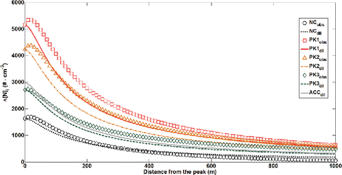
Figure 4. (a) The coagulational sink (m−1) and (b) coagulational loss rates (dN/dx, particles·cm−3·m−1) with plume travel distance for each size bin (NC: circles and dotted line (black); PK1: squares and solid line (red); PK2: triangles and dash-dotted line (orange); PK3: diamonds and dashed line (green); ACC: solid grey). The mean diameters of NC (5.6–8.7 nm), PK1 (8.7–13.3 nm), PK2 (13.3–23.7 nm), PK3 (23.7–42.1 nm), ACC (>42.1 nm) particles are 7.7, 10.9, 17.8, 32.8, and 72.2 nm, respectively. Lines represent Brownian coagulation process and symbols represent enhanced coagulation due to van der Waals and viscous forces (VDW).
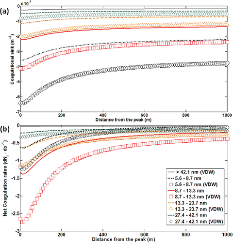
Figure 5. Calculated coagulation enhancement factors (EnF) with varying Hamaker coefficients, A·(kB·T)−1 for a 10.9 nm particle coagulating with different particle sizes. Particles were assumed to have density of 1.2 g·cm−3 and calculations are for 1 atm and 300 K. Symbols denote calculated data points, and dotted lines represent the best-fit results in the form of Equation (Equation17[17] ).
![Figure 5. Calculated coagulation enhancement factors (EnF) with varying Hamaker coefficients, A·(kB·T)−1 for a 10.9 nm particle coagulating with different particle sizes. Particles were assumed to have density of 1.2 g·cm−3 and calculations are for 1 atm and 300 K. Symbols denote calculated data points, and dotted lines represent the best-fit results in the form of Equation (Equation17[17] ).](/cms/asset/4c7c87cd-3e20-4817-9142-e07141c224aa/uast_a_1155104_f0005_oc.gif)
Figure 6. Dry depositional loss rates for each particle size bin with varying vertical plume length H (symbols) and with a fixed H of 20 m (lines with subscript ‘H = 20 m’ in legend). For variable mixing heights, H is defined as the height below which 90% of freeway UFP emissions were confined. Dry deposition velocities were calculated with a parameterization in Petroff and Zhang Citation(2010) under the conditions of 0.7 m/s wind speed and 0.21 m/s friction velocity.
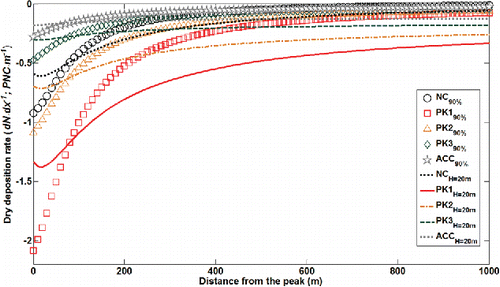
Figure 7. Unexplained particle number variations with plume travel distance from the peak (dN/dx) for size-segregated UFP with an assumption of (A·(kB·T)−1 = 150). Subscripts P-Z (symbols) and S-P (lines) denote the dry deposition parameterization methods in Petroff and Zhang Citation(2010) and Seinfeld and Pandis Citation(1998), respectively. A dark-colored (blue) ellipse shows the regime in which additional losses (likely evaporation) are needed to close the number budget and a light-colored (yellow) rectangular area shows the range where net production of UPF (likely due to a combination of growth of sub-5.6 nm particles via coagulation/condensation growth, and potentially nucleation of new particles and subsequent growth) is needed to balance the observations.
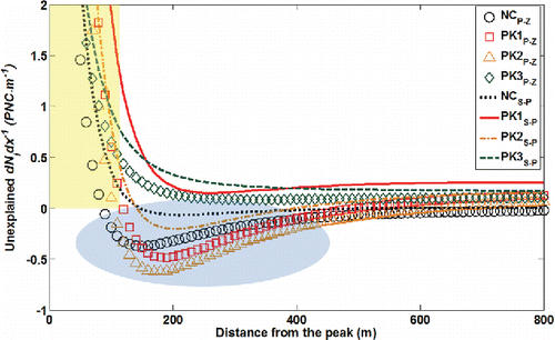
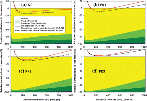
Figure 8. Relative contributions (%) of each dynamical process quantified to the cumulative loss rates of dilution, coagulation, and dry deposition with P-Z parameterization: (a) for NC particles; (b) for PK1, (c) PK2, and (d) PK3. Dilution is colored with light grey (yellow), Brownian coagulation with white (light green), enhanced coagulation with dark grey (dark green), and dry deposition with black (blue). Unexplained particle variation rates relative to the cumulative loss rates are shown with solid (red) (A·(kB·T)−1 = 150) and dashed (black) (A·(kB·T)−1 = 20) curves.
