Figures & data
Figure 1. The geometric standard deviation and maximum penetration particle size (MPPS) under different pressures using the filter parameters in .
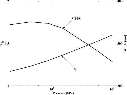
Table 1. Filter parameters from optimization using the Lee and Liu Citation(1982) correlation.
Figure 2. Schematic diagram of the experimental setup used for the low-pressure filter tests. For particles smaller than 300 nm, the DMA sheath and aerosol flows were set to 10 and 1.0 l min−1, respectively. For larger particles, the DMA sheath and aerosol flows were set as 3.75, 0.375, l min−1, respectively.
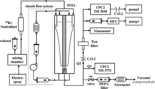
Table 2. The parameters of the sucrose particles generated from the electrospray for the different filter tests.
Figure 3. The counting efficiency of CPC2 (TSI 3010) as a function of pressure and particle size for varying temperature difference (17 and 25°C) between the CPC condenser and saturator. Also, shown are the data from Zhang and Liu (1991, labeled ZL; for CPC model TSI 3760) and from Takegawa and Sakurai (2011, labeled TS; for CPC model TSI 3771).
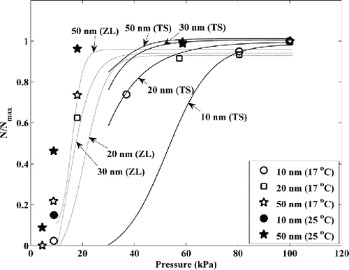
Figure 4. The filter penetration data at different operating conditions (a) 101.3 kPa with flow rates of 1.0, 5.5, and 8.8 l min−1; (b) 57.3 kPa with flow rates of 1.0 and 1.83 l min−1; (c) 15.5 kPa with flow rates of 1.0, 4.0, and 7.82 l min−1; (d) 8.7 kPa with 1.0, 1.95, and 7.85 l min−1; (e) 4.5 kPa with 1.7 and 3.76 l min−1; (f) constant flow rate (1.0 l min−1) under different pressures, 101.3, 57.3, 15.5, and 8.7 kPa. The error bars represent the standard deviation of three repeated experiments. The lines represent the log-scale lognormal distribution (He et al. Citation2015) fit to the experimental data.
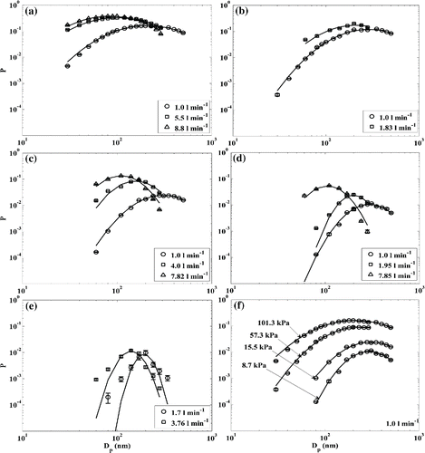
Table 3. Filter penetration curve parameters and pressure drop across the metal filter under different operating pressures.
Table 4. Multivariable regression parameters for MPPS, σfg, and Pmax.
Figure 5. Filter penetration measurements made with non-spherical particles from a spark generator and near-spherical electro-sprayed particles under the same operating conditions.
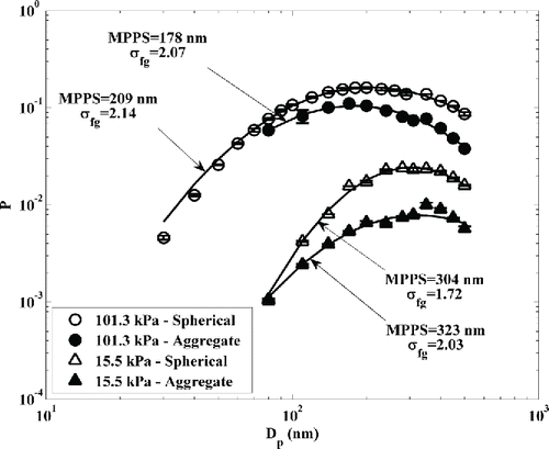
Figure 6. Comparison of filtration efficiency data at 101.3 kPa, obtained from the current study, and theoretical predictions, using the correlation of Lee and Liu Citation(1982). The filter parameters are optimized to ensure minimal error in the calculated filter efficiencies over the entire range of correlation parameter values.
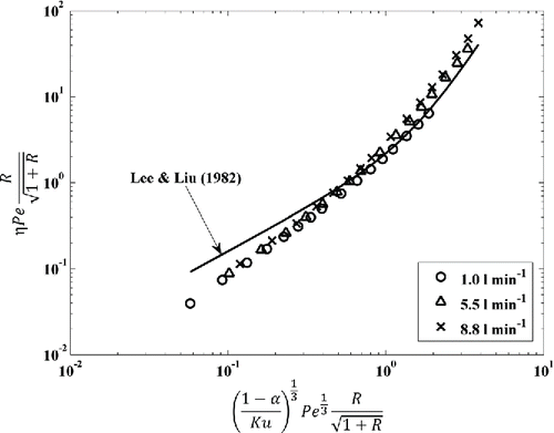
Figure 7. Filter penetration predictions based on the filtration theory of (a) Lee and Liu Citation(1982) and the modified version (Liu and Rubow 1990); (b–f) Dhaniyala and Liu Citation(2001). Theoretical filter penetrations are calculated considering no-slip and slip boundary conditions for the pressure conditions of (b) 101.3 kPa; (c) 57.3 kPa; (d) 15.5 kPa; (e) 8.7 kPa; (f) 4.5 kPa. The darker lines are predictions based on no-slip boundary condition, and the lighter ones are prediction based on slip boundary condition.
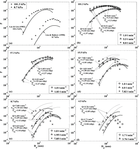
Table 5. Theoretical expressions used for calculation of single fiber efficiency based on different capture mechanisms.
Figure 8. The relative first-norm error in theoretical prediction of particle penetration using no-slip boundary condition as a function of particle Stokes number. The filled markers are the prediction errors using the according to Equation Equation(2)
[2] , while the open circles are the prediction errors using the
according to Equation Equation(3)
[3] .
![Figure 8. The relative first-norm error in theoretical prediction of particle penetration using no-slip boundary condition as a function of particle Stokes number. The filled markers are the prediction errors using the according to Equation Equation(2)[2] , while the open circles are the prediction errors using the according to Equation Equation(3)[3] .](/cms/asset/5e3fd2f8-1d12-45c3-a6f3-c4d01dfb533d/uast_a_1162902_f0008_b.gif)
