Figures & data
Figure 1. A scanned image of the cut-filler shape and size in a tobacco column used in this study. The cut-fillers were scanned by a printer (Hewlett Packard, Palo Alto, CA, USA, C5280) and analyzed by an image processing software (MathWorks Inc., Natick, MA, USA, Matlab).
Table 1. The physical properties of sample cigarettes.
Figure 2. Experimental diagram of the measurement for particle filtration efficiency.
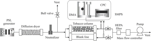
Figure 3. Schematic drawings of the measurement for filtration efficiency during burning.
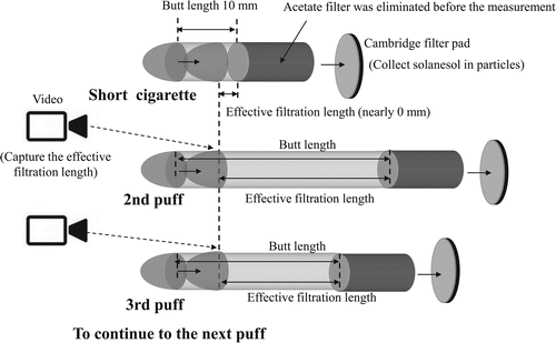
Figure 4. Comparison results between the PSL logarithmic penetration ratio and the smoke components logarithmic penetration ratio.
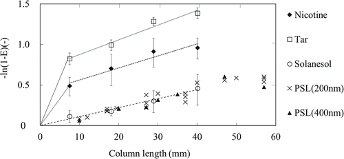
Figure 5. The actual filtration efficiency and the predicted filtration efficiency of each reference through a tobacco column. (a) Flow velocity vs. filtration efficiency (PSL: 200 nm) and (b) PSL particle size vs. filtration efficiency (flow volume: 1.05 L/min).
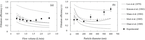
Table 2. The dominant collection mechanisms under the experimental conditions.
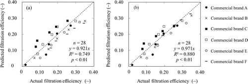
Figure 6. Comparison results between the experimental filtration efficiency and the predicted filtration efficiency calculated by the modified equations. (a) Flow velocity vs. filtration efficiency (PSL: 200 nm) and (b) PSL particle size vs. filtration efficiency (flow volume: 1.05 L/min).
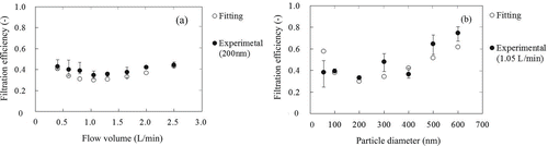
Table 3. The shape-size factor and the distribution factor determined through each of the measurements.
Figure 7. Experimental results of sieve measurements with the commercial brands. (a) Weight frequency of log-normal size distribution and (b) inverse standard normal cumulative distribution (NORMSINV) vs. log minus sieve size.
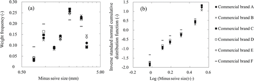
Figure 8. Relationships between the filtration efficiency under the condition of PSL: 200 nm and flow volume: 1.05 L/min and (a) the shape-size factor, (b) the distribution factor, and (c) the average granule size.
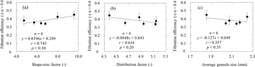
Figure 9. Relationships between the filtration efficiency under the condition of PSL: 200 nm and flow volume: 1.65 L/min and (a) the shape-size factor, (b) the distribution factor, and (c) the average granule size.
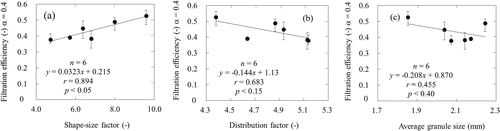
Figure 10. Comparison results of the filtration efficiency during burning with commercial product A under three types of smoking conditions.
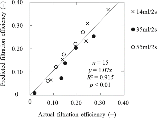
Figure 11. Comparison results of filtration efficiency during burning with commercial products under the condition of ISO. (a) Predicted without the shape-size factor and (b) predicted with the shape-size factor.