Figures & data
Figure 1. Schematic diagram of the mCAMS method.
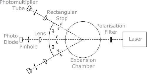
Figure 2. Typical set of normalized scattered light fluxes and light attenuation A, that is, the ratio of total light flux
measured during expansion to
measured before expansion.
is simultaneously monitored at light scattering angles θ = 10°, 15°, 20°, 25°, and 30°, which are given with different hues (colors). Light fluxes were measured during growth of ambient aerosol particles in n-propanol vapor. The droplet number concentration was about 5 × 102 cm−3.
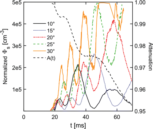
Figure 3. Theoretical (top) and experimental (bottom) scattered light fluxes for five different light scattering angles θ.
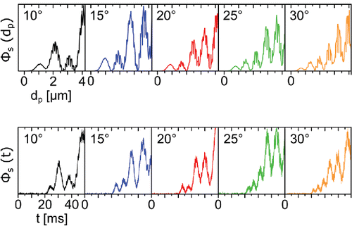
Figure 4. Experimental droplet growth data (crosses) and theoretical droplet growth curves (lines) calculated for three different vapor supersaturation ratios S. The absolute pressure before expansion was 985.5 mbar, the expansion ratio 1.37, the temperature after expansion 2.61°C and the droplet number concentration after expansion 5 × 104 cm−3.
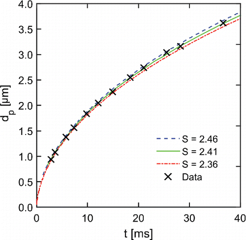
Figure 5. Normalized scattered light flux measured at 15° forward scattering direction. Note the y-axis is scaled logarithmically. The first Mie maximum appearing at around 25 ms represents heterogeneously formed droplets (Nc ∼ 103 cm−3). The third maximum (t ∼ 35 ms) corresponds to homogeneously formed droplets (Nc ∼ 105 cm−3).
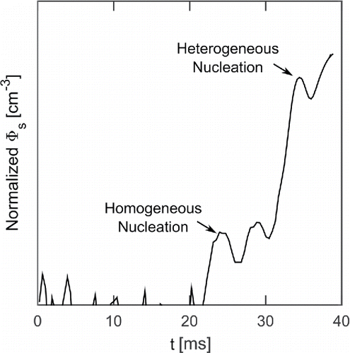
Figure 6. Flow diagram of vSANC.
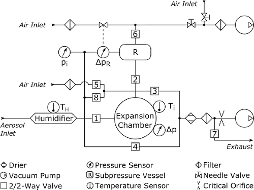
Figure 7. A schematic diagram of the experimental setup for instrument characterization.
Figure 8. Size dependent CPC counting efficiencies of positively charged ammonium sulfate particles. Diamonds (black) refer to vSANC counting efficiency data. Circles (green) and stars (red) are activation efficiencies of an ultrafine CPC (modified TSI Model 3025; Iida et al. Citation2009) and a nCNC (Airmodus Model A11), respectively, both using diethylene glycol as working fluid.
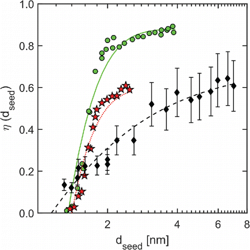
Figure 9. vSANC counting efficiency as a function of seed particle diameter for charged (solid circles) and neutral (open circles) silver particles.
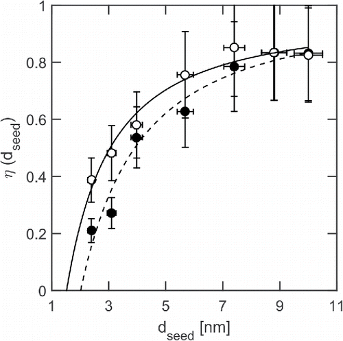
Figure 10. vSANC counting efficiency of positively charged tungsten oxide particles. Stars (blue) and diamonds (red) refer to expansion chamber temperatures of 15°C and 25°C, respectively.
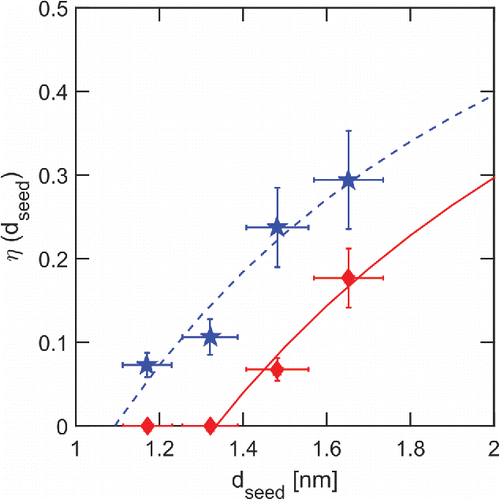
Figure 11. N-propanol onset saturation ratio as a function of geometric seed particle diameter
. Stars and circles represent experimentally determined onset saturation ratios of n-propanol vapor on tungsten oxide and silver seed particles, respectively. Open circles (red) represent neutral seed particles, while all other data were obtained with positively charged seed particles. Colors blue and red refer to expansion chamber temperatures of 15°C and 25°C, respectively. Black stars are experimental data reported by Winkler et al. (Citation2008a).
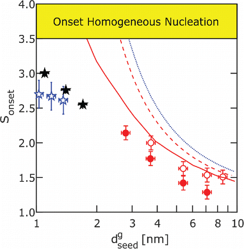
Table 1. Averaged vSANC size bin margins for 23 April 2014.
Figure 12. N-propanol saturation ratios S before (open symbols) and after (solid symbols) expansion during field measurements (23 April 2014, ,
).
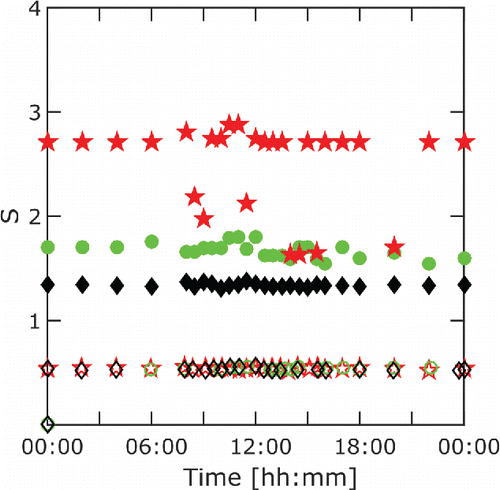
Figure 13. vSANC (top), DMPS (bottom, 3–1000 nm), and nCNC (bottom, 1–3 nm) contour plots from 23 April 2014.
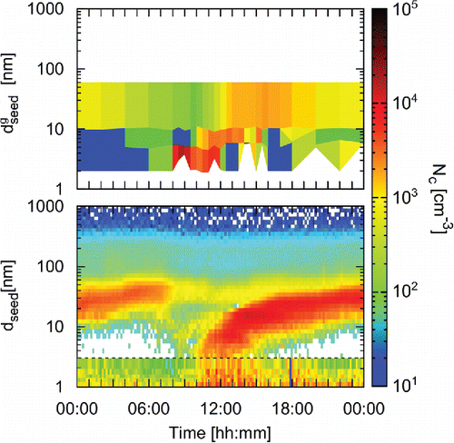
Figure 14. vSANC (top), DMPS (bottom, 3–1000 nm), and nCNC (bottom, 1–3 nm) contour plots from 3 May 2014.
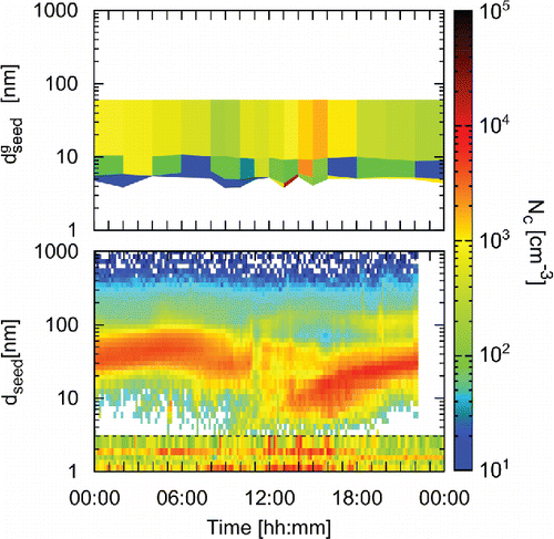
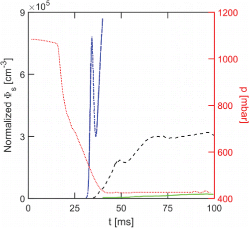
Figure 15. Influence of RH on the onset of homogeneous nucleation inside the particle free expansion chamber at constant expansion ratio. Dash-dotted (blue), dashed, and solid (green) lines represent all-campaign averages of normalized experimental 15° Mie curves measured at about 90, 45, and 25% ambient RH. Heights of first Mie maxima correspond to about 7.8 × 105 cm−3, 1.8 × 105 cm−3, and <103 cm−3 homogeneously formed droplets at 90, 45, and 25% ambient RH, respectively. The dotted (red) line shows the chamber pressure.