Figures & data
Figure 1. Schematic diagram of the real-time mass distribution measuring instrument. An external pump is used to draw the 10 L · min−1 inlet flow and the 5 L · min−1 sheath flow for the dryer. Two critical orifices are used to control the two flow rates.
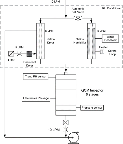
Figure 2. Performance of the RH conditioner. +40°C and +1°C represent the operational set point of the heater as 40°C and 1°C above the temperature at the QCM impactor inlet. The symbols represent measured RH values. The dark solid lines represent the actual operating regions of the RH conditioner. The gray dashed lines are linear fittings of the experiment data points.
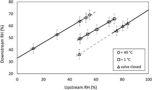
Table 1. QCM cascade impactor design and operating parameters.
Figure 3. Experimental setup for QCM validation.
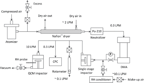
Figure 4. Comparison of the QCM-based aerosol mass measurement with CPC-based mass. Horizontal axis shows the total mass calculated by Equation (Equation2[2] ). Vertical axis shows the total mass calculated by Equation (Equation1
[1] ). The particle sizes are mobility diameters. The horizontal uncertainty comes from the counting efficiency of the CPC, which is less than 3%. The vertical uncertainty comes from the noise of the QCM frequency, which corresponds to about 25 ng in mass. All the data points in the figure were collected in the RH range between 40% and 50%. The comparisons between the two methods during the test as a function of time for the data points of 700 nm ammonium sulfate, 364 nm sodium chloride, 500 nm PSL, and 700 nm oleic acid are shown in Section S1 of the online supplementary information as examples.
![Figure 4. Comparison of the QCM-based aerosol mass measurement with CPC-based mass. Horizontal axis shows the total mass calculated by Equation (Equation2[2] ). Vertical axis shows the total mass calculated by Equation (Equation1[1] ). The particle sizes are mobility diameters. The horizontal uncertainty comes from the counting efficiency of the CPC, which is less than 3%. The vertical uncertainty comes from the noise of the QCM frequency, which corresponds to about 25 ng in mass. All the data points in the figure were collected in the RH range between 40% and 50%. The comparisons between the two methods during the test as a function of time for the data points of 700 nm ammonium sulfate, 364 nm sodium chloride, 500 nm PSL, and 700 nm oleic acid are shown in Section S1 of the online supplementary information as examples.](/cms/asset/973efa26-42cd-4d7a-b5f1-6a45068ec429/uast_a_1213790_f0004_b.gif)
Figure 5. Setup for QCM impactor calibration for stages 2 to 6.
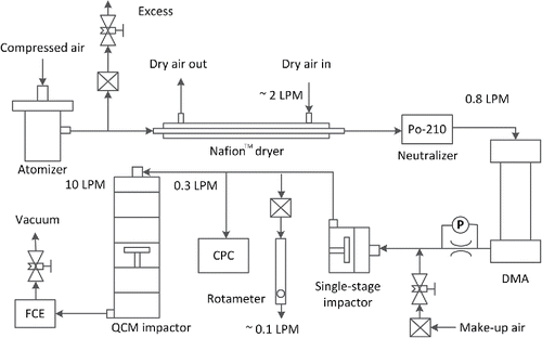
Figure 6. Collection efficiency curves for the QCM impactor inlet and six stages. Solid lines are the cumulative lognormal distribution functions fitted to the experimental data points.
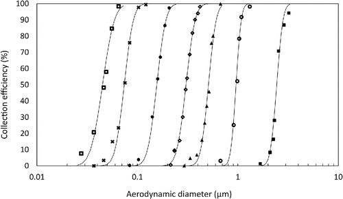
Figure 7. Mass on each stage as a function of time during a test sampling ambient outdoor air.
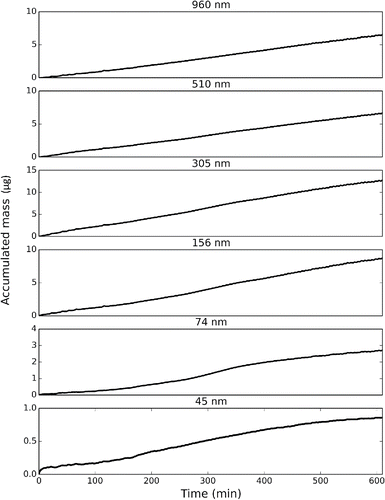
Figure 8. Particle deposition on each stage after 10 h of ambient air sampling. Cutpoint of each stage is shown on the bottom right corner.
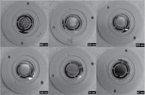
Figure 9. Mass collected on each impactor stage during a 40-min sampling interval of an ambient outdoor aerosol with a PM2.5 concentration of 4 μg · m−3. A data point was taken every 20 s. The top plot shows the RH value at the inlet of the impactor. The ambient RH was below 40% during the time of sampling.
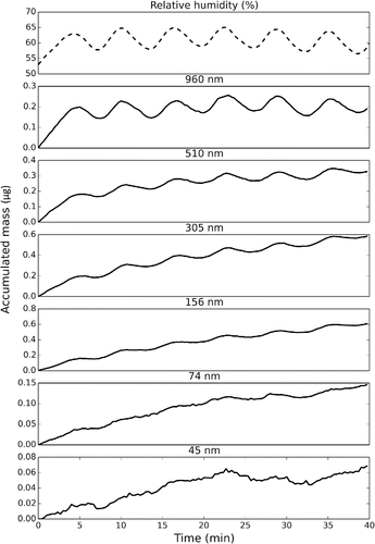
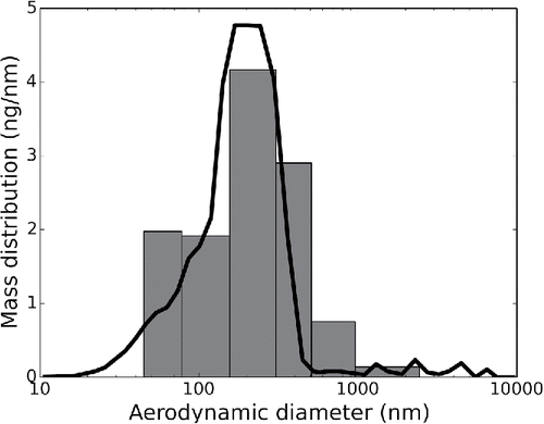
Figure 10. Mass distributions measured by the QCM impactor (bars) and by the WPS (line).