802
Views
11
CrossRef citations to date
0
Altmetric
Original Articles

Using a new inversion matrix for a fast-sizing spectrometer and a photo-acoustic instrument to determine suspended particulate mass over a transient cycle for light-duty vehicles

, , , , , , , , , & show all
Pages 1227-1238 | Received 18 Feb 2016, Accepted 28 Aug 2016, Published online: 11 Oct 2016

Figures & data

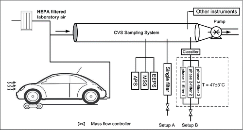
Figure 1. Schematic of laboratory setup at VERL.

Figure 1. Schematic of laboratory setup at VERL.

Table 1. Summary of the testing specification.

Figure 2. PM emission rate determined by gravimetric method (MGrav), IPSD method with Default (MIPSD_Default), and Soot Matrix (MIPSD_Soot), and soot emission rate determined by MSS (Msoot) for the individual test with each test vehicle. For tests in (a), the gravimetric method adopted filter setup A. For tests in (b), the gravimetric method adopted filter setup B. Emission rates of the PFI and LDD vehicles were presented on the right y-axis.
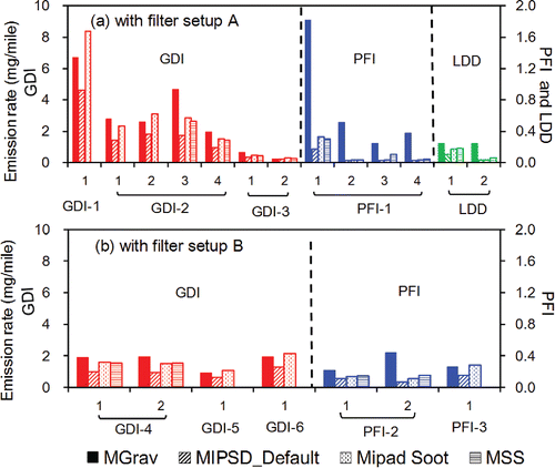
Figure 2. PM emission rate determined by gravimetric method (MGrav), IPSD method with Default (MIPSD_Default), and Soot Matrix (MIPSD_Soot), and soot emission rate determined by MSS (Msoot) for the individual test with each test vehicle. For tests in (a), the gravimetric method adopted filter setup A. For tests in (b), the gravimetric method adopted filter setup B. Emission rates of the PFI and LDD vehicles were presented on the right y-axis.

Figure 3. FTP cycle-averaged particle size distributions for vehicle (a) GDI-2, (b) PFI-2, and (c) LDD with EEPS Default and Soot Matrices. Dashed and solid lines present lognormal fitted size distribution of nucleation and accumulation mode particles, respectively, by EEPS Soot Matrix.
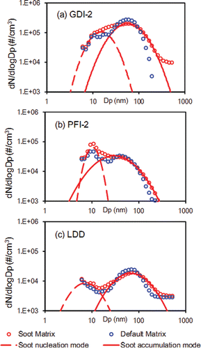
Figure 3. FTP cycle-averaged particle size distributions for vehicle (a) GDI-2, (b) PFI-2, and (c) LDD with EEPS Default and Soot Matrices. Dashed and solid lines present lognormal fitted size distribution of nucleation and accumulation mode particles, respectively, by EEPS Soot Matrix.

Table 2. Parameters for bi-modal fit of FTP cycle from three vehicles.

Figure 4. Correlation of PM mass emission rate determined by IPSD method (MIPSD) and gravimetric filter (MGrav): (a) tests with filter setup A for GDI vehicles, (b) tests with filter setup A for PFI vehicles, the first test on PFI-1 is excluded; (c) tests with filter setup B for GDI vehicles; and (d) tests with filter setup B for the PFI vehicles. Two green lines in (a) represent the regression lines excluding the test with vehicle GDI-1, which has an emission rate of 6.7 mg/mile. Regression lines with intercepts are presented in Figure S6 in the SI.
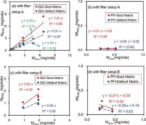
Figure 4. Correlation of PM mass emission rate determined by IPSD method (MIPSD) and gravimetric filter (MGrav): (a) tests with filter setup A for GDI vehicles, (b) tests with filter setup A for PFI vehicles, the first test on PFI-1 is excluded; (c) tests with filter setup B for GDI vehicles; and (d) tests with filter setup B for the PFI vehicles. Two green lines in (a) represent the regression lines excluding the test with vehicle GDI-1, which has an emission rate of 6.7 mg/mile. Regression lines with intercepts are presented in Figure S6 in the SI.

Figure 5. Correlation of PM mass emission rate determined by IPSD method (MIPSD) and micro soot sensor (MSoot) (a) tests with the GDI vehicles, (b) tests with the PFI vehicles. LDD vehicle is not included because of limited test number ( = 2).
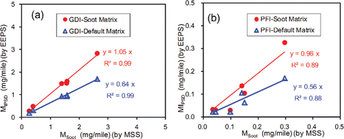
Figure 5. Correlation of PM mass emission rate determined by IPSD method (MIPSD) and micro soot sensor (MSoot) (a) tests with the GDI vehicles, (b) tests with the PFI vehicles. LDD vehicle is not included because of limited test number ( = 2).

Figure 6. Time series and correlations of MIPSD and MSoot over an FTP cycle of vehicle GDI-2.

Figure 6. Time series and correlations of MIPSD and MSoot over an FTP cycle of vehicle GDI-2.

Figure 7. Time series and correlations of MIPSD and MSoot over an FTP cycle of vehicle PFI-2.

Figure 7. Time series and correlations of MIPSD and MSoot over an FTP cycle of vehicle PFI-2.

Figure 8. Time series and correlations of MIPSD and MSoot over an FTP cycle of vehicle LDD.

Figure 8. Time series and correlations of MIPSD and MSoot over an FTP cycle of vehicle LDD.

Figure 9. PM emission rate determined by EEPS Soot Matrix, APS, and gravimetric filter during three tests conducted at HSL. The numbers on the accumulative columns represent the percentage of PM mass determined by APS to total PM mass determined by size distribution method (the summing of APS mass and EEPS mass).
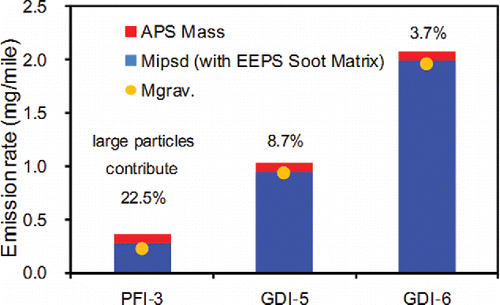
Figure 9. PM emission rate determined by EEPS Soot Matrix, APS, and gravimetric filter during three tests conducted at HSL. The numbers on the accumulative columns represent the percentage of PM mass determined by APS to total PM mass determined by size distribution method (the summing of APS mass and EEPS mass).
Supplemental material

UAST_1239247_Supplemental_File.zip

Download Zip (304.5 KB)

Reprints and Corporate Permissions

Please note: Selecting permissions does not provide access to the full text of the article, please see our help page How do I view content?

To request a reprint or corporate permissions for this article, please click on the relevant link below:

Academic Permissions

Please note: Selecting permissions does not provide access to the full text of the article, please see our help page How do I view content?

Obtain permissions instantly via Rightslink by clicking on the button below:

If you are unable to obtain permissions via Rightslink, please complete and submit this Permissions form. For more information, please visit our Permissions help page.