1,263
Views
6
CrossRef citations to date
0
Altmetric
Articles

Mathematical modeling and numerical simulation of surfactant delivery within a physical model of the neonatal trachea for different aerosol characteristics

, , &
Pages 168-177 | Received 31 Jul 2016, Accepted 07 Oct 2016, Published online: 28 Nov 2016

Figures & data

Figure 1. Computational geometry and boundary conditions for (a) Domain 1 and (b) Domain 2.

Figure 1. Computational geometry and boundary conditions for (a) Domain 1 and (b) Domain 2.

Table 1. Uniform droplet aerodynamic diameter (Da) and mass flow rate (m) for each partial injection, for PFD and surfactant aerosols.

Figure 2. Comparison of experimental and numerical air axial velocity profiles (a) 30 mm beyond the distal tip of the IC and (b) 5 mm beyond the exit of the G0 of the physical model, for a driving pressure of 4 bar.
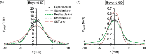
Figure 2. Comparison of experimental and numerical air axial velocity profiles (a) 30 mm beyond the distal tip of the IC and (b) 5 mm beyond the exit of the G0 of the physical model, for a driving pressure of 4 bar.

Table 2. Experimental and numerical results of droplet size characterization 35 mm (surfactant) and 60 mm (PFD) beyond the distal tip of the IC and 10 mm beyond the G0 of the physical model.

Figure 3. Comparison of experimental and numerical cumulative mass based droplet size distribution curves (a) 35 mm (surfactant) and 60 mm (PFD) beyond the distal tip of the IC, and (b) 10 mm beyond the exit of the G0 of the physical model. Beyond IC: Domain 1. Beyond G0: Domain 2.
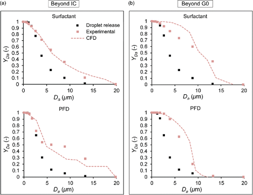
Figure 3. Comparison of experimental and numerical cumulative mass based droplet size distribution curves (a) 35 mm (surfactant) and 60 mm (PFD) beyond the distal tip of the IC, and (b) 10 mm beyond the exit of the G0 of the physical model. Beyond IC: Domain 1. Beyond G0: Domain 2.

Table 3. Numerical results of the percentage distribution of the atomized mass.

Figure 4. Numerical results of mass based droplet size distribution curves at the distal end of the G0 of the physical model. (a) Influence of injected mass flow rate. (b) Influence of injected droplet size.
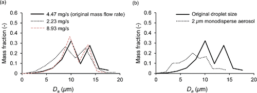
Figure 4. Numerical results of mass based droplet size distribution curves at the distal end of the G0 of the physical model. (a) Influence of injected mass flow rate. (b) Influence of injected droplet size.

Table 4. Numerical results of droplet size characterization just at the distal end of the G0 of the physical model for different surfactant aerosols.

Table 5. Numerical results of the percentage distribution of the atomized mass for different surfactant aerosols.

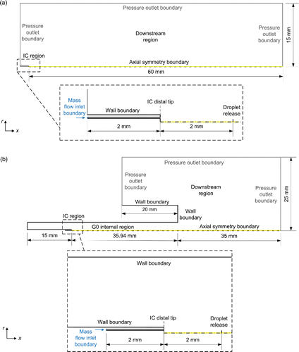
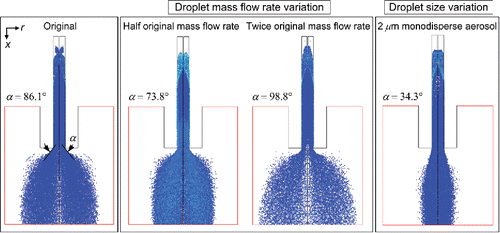
Figure 5. Numerical results of the behavior of surfactant aerosols within the physical model and the aerosol cone angle (α) beyond the G0 for different mass flow rates and droplet sizes.

Figure 5. Numerical results of the behavior of surfactant aerosols within the physical model and the aerosol cone angle (α) beyond the G0 for different mass flow rates and droplet sizes.
Supplemental material

UAST_1255714_Supplementary_File.zip

Download Zip (403.4 KB)

Reprints and Corporate Permissions

Please note: Selecting permissions does not provide access to the full text of the article, please see our help page How do I view content?

To request a reprint or corporate permissions for this article, please click on the relevant link below:

Academic Permissions

Please note: Selecting permissions does not provide access to the full text of the article, please see our help page How do I view content?

Obtain permissions instantly via Rightslink by clicking on the button below:

If you are unable to obtain permissions via Rightslink, please complete and submit this Permissions form. For more information, please visit our Permissions help page.