800
Views
1
CrossRef citations to date
0
Altmetric
Articles

Spatial aerosol flow maldistribution: A design flaw confounding the proper calibration and data interpretation of stages “0” and “1” of the Andersen eight-stage nonviable cascade impactor

&
Pages 409-420 | Received 24 Sep 2016, Accepted 14 Nov 2016, Published online: 20 Dec 2016

Figures & data

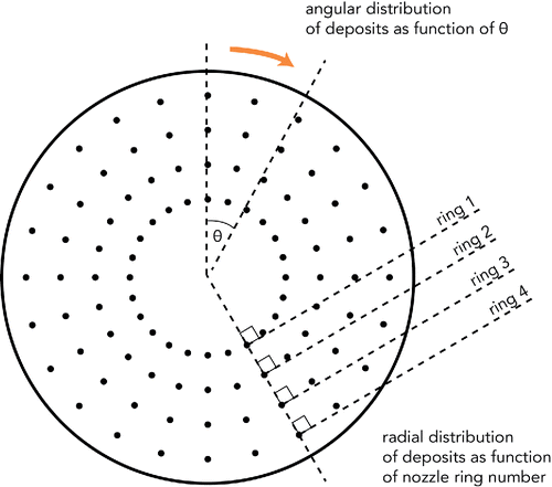
Figure 1. Plan view of Stage 0 or 1 of the ACI defining angular and radial nozzle arrangement.

Figure 1. Plan view of Stage 0 or 1 of the ACI defining angular and radial nozzle arrangement.

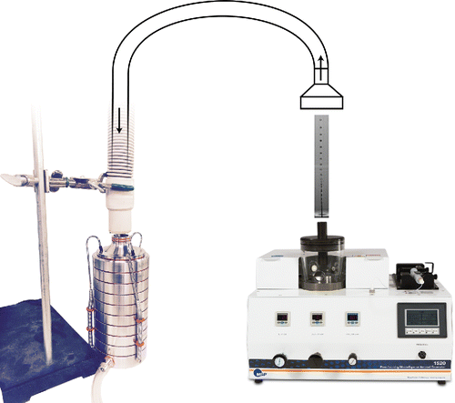
Figure 2. Generation of calibrant particles and introduction to impactor inlet.

Figure 2. Generation of calibrant particles and introduction to impactor inlet.

Figure 3. Measured particle capture efficiency curves for (a) Stages “0” and (b) “1” of the Andersen impactor operated at 28.3 L/min (Roberts and Mitchell Citation2014); the D50 values are 9.0 and 5.8 µm, respectively, in agreement with the generally accepted values (USP, Ph. Eur.).
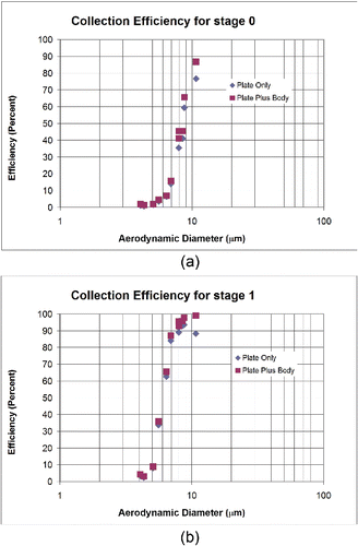
Figure 3. Measured particle capture efficiency curves for (a) Stages “0” and (b) “1” of the Andersen impactor operated at 28.3 L/min (Roberts and Mitchell Citation2014); the D50 values are 9.0 and 5.8 µm, respectively, in agreement with the generally accepted values (USP, Ph. Eur.).

Table 1. Capture of various sizes of monodisperse microsphere calibration aerosols under each concentric ring for collection plates relating to stages “0” and “1” of an ACI operated at 28.3 L/min.

Table 2. Repeatibility of deposit recovery from ACI stages “0” and “1”; the mean and standard deviation for deposit mass fraction (%) are identified in relation to nozzle ring number.

Figure 4. Air patterns in laminar jet expansion (simplified from Table 7–6 of Blevins, Citation1984).
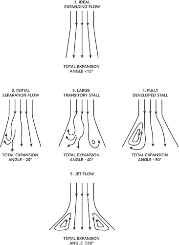
Figure 4. Air patterns in laminar jet expansion (simplified from Table 7–6 of Blevins, Citation1984).

Figure 5. Schematic diagram of effect of particle inertia on localized mass concentration and size distribution of particles in the cone expansion inlet of the ACI; the larger inertia of the largest particles concentrates them in the central region above the entry to the nozzles, whereas the finest particles move with the circulating flow toward the periphery.
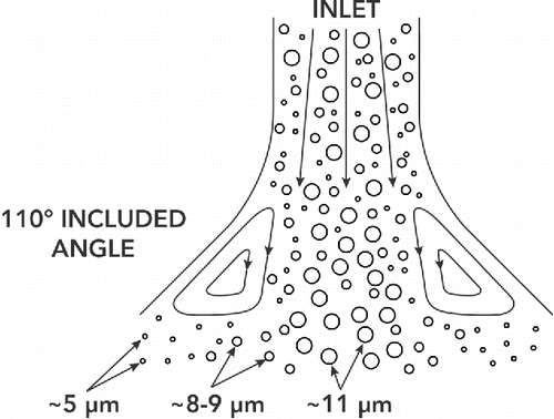
Figure 5. Schematic diagram of effect of particle inertia on localized mass concentration and size distribution of particles in the cone expansion inlet of the ACI; the larger inertia of the largest particles concentrates them in the central region above the entry to the nozzles, whereas the finest particles move with the circulating flow toward the periphery.
Supplemental material

UAST_1263385_Supplementary_File.zip

Download Zip (1.3 MB)

Reprints and Corporate Permissions

Please note: Selecting permissions does not provide access to the full text of the article, please see our help page How do I view content?

To request a reprint or corporate permissions for this article, please click on the relevant link below:

Academic Permissions

Please note: Selecting permissions does not provide access to the full text of the article, please see our help page How do I view content?

Obtain permissions instantly via Rightslink by clicking on the button below:

If you are unable to obtain permissions via Rightslink, please complete and submit this Permissions form. For more information, please visit our Permissions help page.