Figures & data
Table 1. Characteristics of test vehicles.
Figure 1. Experimental setup. Dashed lines indicate optional parts. APC = AVL particle counter; CPC = condensation particle counter; CS = catalytic stripper; CVS = constant volume sampler; DB = dilution bridge; EJ = ejector; ET = evaporation tube; nCNC = nano condensation nucleus counter; TD = thermodenuder.
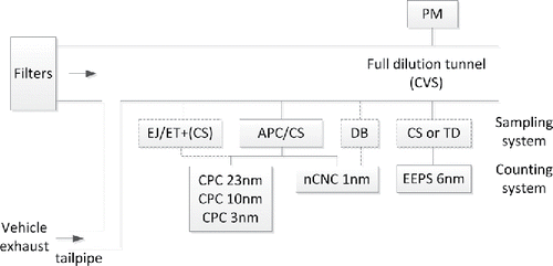
Figure 2. Penetration curves following the correction with the mean PCRF (average of 30, 50, 100 nm). Symbols are experimental data. ‘Sample tubing’ refers to a hose of 40 cm length, inner diameter of 4 mm and flow rate of 1.5 l/min. Dashed lines are only there to help the eye. Open symbols are soot-like particles (propane diffusion flame for APC/CS and spark-discharged graphite for EJ/ET), while solid symbols are silver particles. Error bars indicate min-max of two measurements on different days.
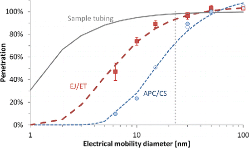
Figure 3. Real-time measurements in the cold start part of the R47 with the 2-stroke moped using E5 fuel (Mo_2s). EEPS and nCNC were measuring total PN, while the APC/CS was measuring SPN.
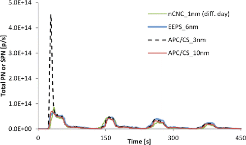
Figure 4. Emission levels of the 4-stroke moped as determined by different instruments for (a) cold part of the R47 cycle (first four sub-cycles) and (b) hot part of the R47 cycle (last 4 sub-cycles). Error bars show the variability of five tests conducted on different days. Only one test was available for the EJ/ET system and with the 3 nm CPC and the 1 nm nCNC. Arrows show the percentage differences between the two systems for uncorrected or corrected loss concentrations. Details of the corrections presented in the text.
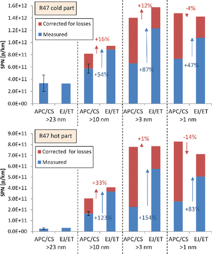
Figure 5. Reported sub-23 nm fraction of solid particles for different vehicles (from Giechaskiel and Martini Citation2015) as estimated by the differences of the 10 nm and 23 nm condensation particle counters (CPCs) of APC or APC/CS systems. Every point is an average of many tests with a specific vehicle, typically with the future type approval cycles. Solid (and bigger) symbols are the results of this study. All sub-23 nm fractions in this figure haven't been corrected for losses (i.e., a factor between 1.7 and 2 would be needed, depending on the system used). Vertical dashed line indicates the current limit of 6×10¹¹ p/km for particles >23 nm in diameter. The other line indicates the same limit for particles >10 nm in diameter. All mopeds were 2-stroke unless otherwise specified in the figure.
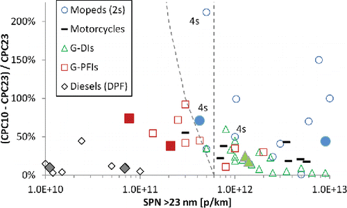
Table 2. PM mass, total PN, SPN emissions and their sub-23 nm particle fractions. The number after the instrument (EEPS, CPC, nCNC) gives the 50% cut-point that was used for the calculations (1, 6, 10, or 23 nm). The APC/CS sub-23 and sub-10 nm fractions have been corrected for losses (correction factor 2 and 10, respectively). Numbers in brackets give one standard deviation from the original measurement multiplied by the loss correction factor. The two columns can be added up to calculate the total sub-23 nm fraction.
Figure 6. Real-time signals of various instruments connected to the CVS with the 4-stroke moped (Mo_4s). Cold start WMTC. Concentrations refer to the CVS. The Geometric Mean Diameter (GMD) is also shown on the right y-axis.
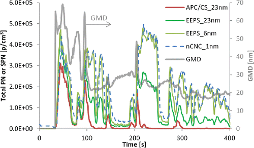
Figure 7. Real-time signals of EEPS and nCNC during an NEDC with the G-PFI vehicle (fuel E5). Both instruments were connected to the CVS. nCNC saturated at 5×10⁵ p/cm3.
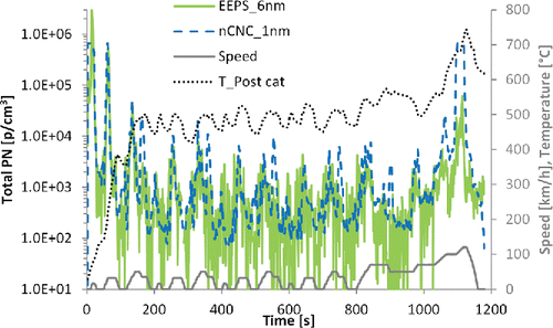
Figure 8. Size distributions measured at the full dilution tunnel (CVS) with an EEPS. Concentrations refer to the tailpipe (i.e., corrected with the CVS dilution of the specific seconds taken). ‘Start’ refers to the second acceleration and ‘end’ refers to the high speed part of the cycles. ‘Min’ refers to the limit of detection of EEPS (multiplied by the dilution at the CVS). The ‘Soot’ matrix was used for data inversion.
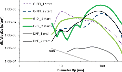
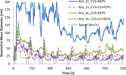
Figure 9. Geometric mean diameter throughout R47 test cycles for mopeds as measured by an EEPS directly from the full dilution tunnel (CVS) or through a catalytic stripper (CS). The ‘Soot’ matrix was used.