976
Views
10
CrossRef citations to date
0
Altmetric
Articles

Design, simulation, and characterization of a radial opposed migration ion and aerosol classifier (ROMIAC)

ORCID Icon, , , & ORCID Icon
Pages 801-823 | Received 05 Jun 2016, Accepted 01 Feb 2017, Published online: 04 May 2017

Figures & data

Figure 1. (a) Simplified diagram of balanced drag, FD, and electric, FE, forces acting on a particle of mobility Z* in the ROMIAC classification region, resulting in a particle streamline that is parallel to the sample flow direction. (b) Simplified diagram of aerosol and cross-flow fluid velocities (ua and ucf, respectively) and electrical migration velocity, vmig, acting on a particle of mobility Z*. Low operation results in fluid streamlines that significantly deviate from vertical. Particles of mobility Z* will thus experience a high advective velocity (relative to the cross-flow velocity) from sample inlet to outlet, increasing the transmission of all particles, and resulting in lower resolution. (c) High operation results in nearly vertical fluid streamlines, discriminating more heavily against the transmission of particles that are not of mobility Z*.
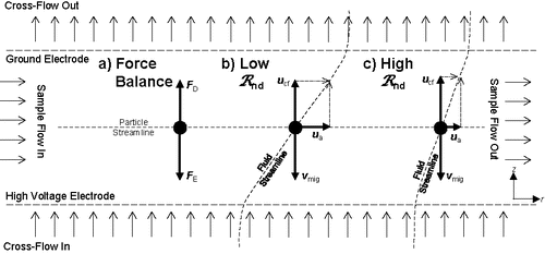
Figure 1. (a) Simplified diagram of balanced drag, FD, and electric, FE, forces acting on a particle of mobility Z* in the ROMIAC classification region, resulting in a particle streamline that is parallel to the sample flow direction. (b) Simplified diagram of aerosol and cross-flow fluid velocities (ua and ucf, respectively) and electrical migration velocity, vmig, acting on a particle of mobility Z*. Low operation results in fluid streamlines that significantly deviate from vertical. Particles of mobility Z* will thus experience a high advective velocity (relative to the cross-flow velocity) from sample inlet to outlet, increasing the transmission of all particles, and resulting in lower resolution. (c) High operation results in nearly vertical fluid streamlines, discriminating more heavily against the transmission of particles that are not of mobility Z*.

Figure 2. Schematic of ROMIAC aerosol introduction, classification region, and classified aerosol outlet. Particles are introduced via a tangential inlet tube to be azimuthally distributed through a thin knife-edge gap into the classification region, where particles follow characteristic trajectories based on the degree of balance of drag and electric forces experienced. Particles of mobility Z* will be advected toward the center and extracted through the outlet. Key dimensions that define the classification region are indicated. The origin of the coordinate system is designated to be the center of the incoming cross-flow electrode.
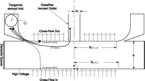
Figure 2. Schematic of ROMIAC aerosol introduction, classification region, and classified aerosol outlet. Particles are introduced via a tangential inlet tube to be azimuthally distributed through a thin knife-edge gap into the classification region, where particles follow characteristic trajectories based on the degree of balance of drag and electric forces experienced. Particles of mobility Z* will be advected toward the center and extracted through the outlet. Key dimensions that define the classification region are indicated. The origin of the coordinate system is designated to be the center of the incoming cross-flow electrode.

Figure 3. (a) Cutaway view and (b) photograph of ROMIAC with key features numbered. Overall exterior dimensions are 10.5 cm in height and 11.4 cm in diameter. (1) Aerosol inlet tube; (2) tangential inlet to distribution racetrack; (3) distribution knife-edge; (4) dielectric spacer; (5) classified aerosol outlet tube; (6) incoming cross-flow port; (7) high voltage porous electrode; (8) electrically grounded porous electrode; (9) outgoing cross-flow port.
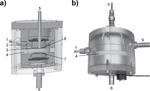
Figure 3. (a) Cutaway view and (b) photograph of ROMIAC with key features numbered. Overall exterior dimensions are 10.5 cm in height and 11.4 cm in diameter. (1) Aerosol inlet tube; (2) tangential inlet to distribution racetrack; (3) distribution knife-edge; (4) dielectric spacer; (5) classified aerosol outlet tube; (6) incoming cross-flow port; (7) high voltage porous electrode; (8) electrically grounded porous electrode; (9) outgoing cross-flow port.

Figure 4. Example COMSOL Multiphysics™ solutions for the case of 2 lpm/20 lpm/10/10 nm. Aerosol inlet and outlet tube extremities are cropped out of view. Color scales are restricted in range to distinguish areas of interest. Physical features of interest that may not be obvious are labeled. (a) Section view showing axial component of fluid flow velocity, uz. Lines show fluid flow velocity streamlines that originate from the cross-flow inlet, and are truncated at the converging region near the aerosol outlet for clarity. Note that the vertical velocity increases approaching the centered aerosol outlet. Dashed lines z1 and z2 mark sections corresponding to those in (b). (b) Overhead view showing non-axial component of fluid flow velocity, . Dashed circles z1 and z2 correspond to the cut planes in (a). The white ring between z1 and z2 indicates the absence of data, not zero velocity. Note that the non-vertical velocity increases approaching the centered aerosol outlet. (c) Section view showing the normalized electric potential solution. Lines show electric field lines that originate from the high voltage electrode surface. (d) Section view showing the particle concentration solution at a voltage corresponding to Z*.
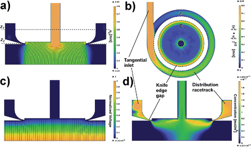
Figure 4. Example COMSOL Multiphysics™ solutions for the case of 2 lpm/20 lpm/10/10 nm. Aerosol inlet and outlet tube extremities are cropped out of view. Color scales are restricted in range to distinguish areas of interest. Physical features of interest that may not be obvious are labeled. (a) Section view showing axial component of fluid flow velocity, uz. Lines show fluid flow velocity streamlines that originate from the cross-flow inlet, and are truncated at the converging region near the aerosol outlet for clarity. Note that the vertical velocity increases approaching the centered aerosol outlet. Dashed lines z1 and z2 mark sections corresponding to those in (b). (b) Overhead view showing non-axial component of fluid flow velocity, . Dashed circles z1 and z2 correspond to the cut planes in (a). The white ring between z1 and z2 indicates the absence of data, not zero velocity. Note that the non-vertical velocity increases approaching the centered aerosol outlet. (c) Section view showing the normalized electric potential solution. Lines show electric field lines that originate from the high voltage electrode surface. (d) Section view showing the particle concentration solution at a voltage corresponding to Z*.

Table 1. Nominal flow conditions and particle diameters for simulations and experiments in this study. Pemig and Pemigβ values are calculated for convenience in using .

Figure 5. Experimental setup diagrams for tandem-ROMIAC measurements. (a) Electrosprayed TAAX molecular standards calibration. (b) Atomized NaCl calibration.
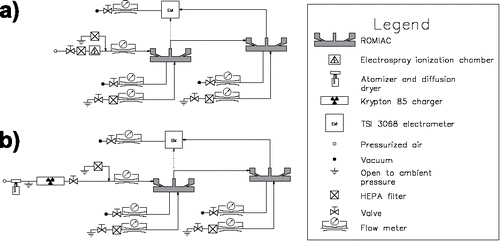
Figure 5. Experimental setup diagrams for tandem-ROMIAC measurements. (a) Electrosprayed TAAX molecular standards calibration. (b) Atomized NaCl calibration.

Figure 6. Example measurements (points) and transfer function fits (lines) with listed operating conditions and fitting parameters. Top row: COMSOL Multiphysics™ simulation examples for (a) small DZ at low operation and (b) large DZ at high operation. Middle row: tandem-ROMIAC TAAX measurement examples for (c) small DZ at low operation and (d) small DZ at high operation. Bottom row: tandem-ROMIAC NaCl measurement examples for (e) large DZ at low operation and (f) large DZ at high operation.
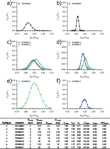
Figure 6. Example measurements (points) and transfer function fits (lines) with listed operating conditions and fitting parameters. Top row: COMSOL Multiphysics™ simulation examples for (a) small DZ at low operation and (b) large DZ at high operation. Middle row: tandem-ROMIAC TAAX measurement examples for (c) small DZ at low operation and (d) small DZ at high operation. Bottom row: tandem-ROMIAC NaCl measurement examples for (e) large DZ at low operation and (f) large DZ at high operation.

Figure 7. Simulation results used to estimate fZ,bias. (a) fu,z (from COMSOL Multiphysics™-driven kinematic particle trajectories) against βnom. Best-fit line is fu,z = 1.01 + 0.11βnom. (b) fZ,bias against estimated fu,z colored by Pemig. (c) 1-to-1 comparison of simulation fZ,bias against those estimated from an empirical function of fu,z and Pemig. For convenience, Pemig values are listed in .
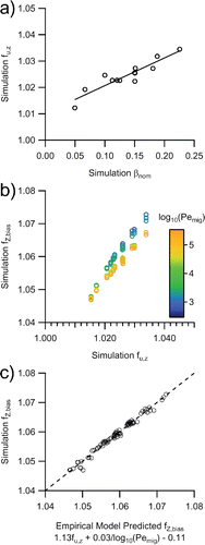
Figure 7. Simulation results used to estimate fZ,bias. (a) fu,z (from COMSOL Multiphysics™-driven kinematic particle trajectories) against βnom. Best-fit line is fu,z = 1.01 + 0.11βnom. (b) fZ,bias against estimated fu,z colored by Pemig. (c) 1-to-1 comparison of simulation fZ,bias against those estimated from an empirical function of fu,z and Pemig. For convenience, Pemig values are listed in Table 1.

Figure 8. COMSOL Multiphysics™ simulation correction factor relationships, comparison of simulation values to empirical functions, and comparison of experimental values to empirical functions. Error bars in experimental results represent 2 standard deviations of multiple measurements. Top row: (a) simulation fβ against fu,z colored by Pemig. (b) 1-to-1 comparison of simulation fβ against empirical model of fu,z and Pemig. (c) 1-to-1 comparison of experiment-fitted fβ against empirical model of fu,z and Pemig. Middle row: (d) simulation against βeff. (e) 1-to-1 comparison of simulation against empirical model of βeff. (f) 1-to-1 comparison of experiment-fitted against empirical model of βeff. Bottom row: (g) simulation ηtrans against Pemigβeff colored by βeff. (h) 1-to-1 comparison of simulation ηtrans against empirical model of Pemig and βeff. (i) 1-to-1 comparison of experiment-fitted ηtrans against empirical model of Pemig and βeff. For convenience, Pemig and Pemigβ values are listed in .
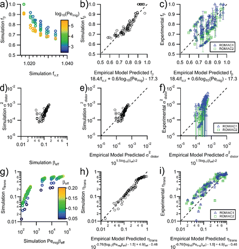
Figure 8. COMSOL Multiphysics™ simulation correction factor relationships, comparison of simulation values to empirical functions, and comparison of experimental values to empirical functions. Error bars in experimental results represent 2 standard deviations of multiple measurements. Top row: (a) simulation fβ against fu,z colored by Pemig. (b) 1-to-1 comparison of simulation fβ against empirical model of fu,z and Pemig. (c) 1-to-1 comparison of experiment-fitted fβ against empirical model of fu,z and Pemig. Middle row: (d) simulation against βeff. (e) 1-to-1 comparison of simulation against empirical model of βeff. (f) 1-to-1 comparison of experiment-fitted against empirical model of βeff. Bottom row: (g) simulation ηtrans against Pemigβeff colored by βeff. (h) 1-to-1 comparison of simulation ηtrans against empirical model of Pemig and βeff. (i) 1-to-1 comparison of experiment-fitted ηtrans against empirical model of Pemig and βeff. For convenience, Pemig and Pemigβ values are listed in Table 1.

Figure 9. (a) Theoretical (lines) and observed simulation and experimental (markers) resolution obtained with the ROMIAC against V and Pemig. Curves and markers for only three values of are displayed for clarity ( 5.3, 10, and 20.2). (b) Theoretical (lines) and observed simulation and experimental (markers) effective relative resolution obtained with the ROMIAC against V and Pemig. Markers for all operating conditions are shown, but curves for only three values of are displayed for clarity ( 5.3, 10, and 20.2). Error bars in experimental results represent 1 standard deviation of multiple measurements. For convenience, Pemig values are listed in .
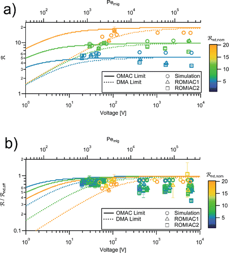
Figure 9. (a) Theoretical (lines) and observed simulation and experimental (markers) resolution obtained with the ROMIAC against V and Pemig. Curves and markers for only three values of are displayed for clarity ( 5.3, 10, and 20.2). (b) Theoretical (lines) and observed simulation and experimental (markers) effective relative resolution obtained with the ROMIAC against V and Pemig. Markers for all operating conditions are shown, but curves for only three values of are displayed for clarity ( 5.3, 10, and 20.2). Error bars in experimental results represent 1 standard deviation of multiple measurements. For convenience, Pemig values are listed in Table 1.

Table 2. Geometry parameters, fitting factors, and typical flow conditions for various DMAs.

Supplemental material

UAST_1315046_Supplemental_File.zip

Download Zip (884.4 KB)

Reprints and Corporate Permissions

Please note: Selecting permissions does not provide access to the full text of the article, please see our help page How do I view content?

To request a reprint or corporate permissions for this article, please click on the relevant link below:

Academic Permissions

Please note: Selecting permissions does not provide access to the full text of the article, please see our help page How do I view content?

Obtain permissions instantly via Rightslink by clicking on the button below:

If you are unable to obtain permissions via Rightslink, please complete and submit this Permissions form. For more information, please visit our Permissions help page.