Figures & data
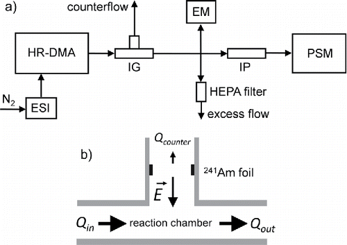
Figure 1. (a) Experimental setup for the neutralization of electrospray-generated mobility standards. ESI (electrospray ion source), HR-DMA (high-resolution DMA), IG (ion gun neutralizer), EM (aerosol electrometer), HEPA (high-efficiency particulate arrestance) filter, IP (ion precipitator), and PSM (particle size magnifier). (b) Schematic view of the ion gun (IG) neutralizer. A 241Am radioactive source produces bipolar ions in the carrier gas. An electric field gradient pulls ions of one polarity into a reaction chamber where the ions can recombine with size-selected clusters originating from the electrospray ion source. A counter flow Qcounter of 0.2 L/min (3.3 × 10⁻⁶ m3/s) ensures that the ions of opposite polarity, which are deflected by the electric field, are efficiently drawn into an exhaust line.

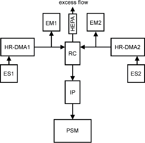
Figure 2. Schematic overview of the experimental setup for the controlled neutralization of well-defined positive and negative electrospray-generated ion clusters. ES1 and HR-DMA1 (UDMA) produce and classify positive ion clusters of a certain size, ES2 and HR-DMA2 (Hermann - DMA) take care of negative polarity ions. EM1 and EM2 are aerosol electrometers, detecting the total number concentration of the classified positive and negative clusters. The airflows containing the positive and negative ion clusters are merged in a recombination cell (RC). An ion precipitator (IP) ensures that no ions obscure the detection of neutral clusters in the particle size magnifier (PSM). The remaining airflow is discarded via a HEPA-filter as excess flow.

Table 1. Cluster properties in the neutralization experiments. Considering two neutralization pathways (Section 2.4), two different final sizes (Dmass and Dvol) of the neutralized clusters are listed.
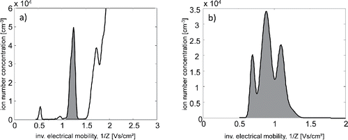
Figure 3. (a) Mobility spectrum of negative MTOA-BF3I clusters. The highlighted peak corresponds to the dimer cluster A−(AB)1. (b) Mobility spectrum of positive ions produced by the ion gun.

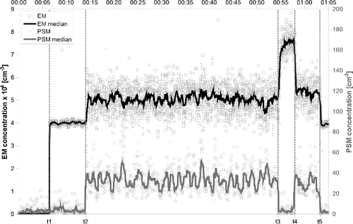
Figure 4. Time series of zero-corrected electrometer and PSM signals during the neutralization experiment of the dimer cluster of MTOA-BF3I.

Figure 5. Time series of electrometer ([−2], [+2]) and PSM signals ([+2, −2]) during the controlled neutralization experiment of the positive and negative dimer clusters of the ionic liquid MTOA-BF3I.
![Figure 5. Time series of electrometer ([−2], [+2]) and PSM signals ([+2, −2]) during the controlled neutralization experiment of the positive and negative dimer clusters of the ionic liquid MTOA-BF3I.](/cms/asset/072d25a2-3f11-46ed-a4ee-3337ba1a3b2d/uast_a_1328103_f0005_b.gif)
Table 2. Cluster properties in the recombination experiments. The size of the recombined, neutral clusters is calculated as Dvol, following again the considerations in Section 2.4.
