541
Views
5
CrossRef citations to date
0
Altmetric
Articles

Preliminary investigation of a water-based method for fast integrating mobility spectrometry

, , &
Pages 1223-1230 | Received 08 Feb 2017, Accepted 28 May 2017, Published online: 07 Jul 2017

Figures & data

Figure 1. Schematic of the water-FIMS system, showing mobility separator, water condensation growth channel and detection zone. The system uses a parallel plate geometry. In this sketch the gap dimension has been greatly magnified with respect to the length.
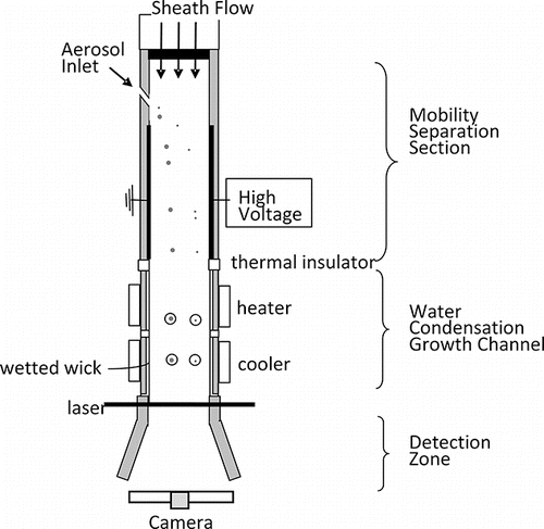
Figure 1. Schematic of the water-FIMS system, showing mobility separator, water condensation growth channel and detection zone. The system uses a parallel plate geometry. In this sketch the gap dimension has been greatly magnified with respect to the length.

Figure 2. CAD image of the water condensation growth channel showing the Active Insulator, Initiator, Moderator, and Optics. Temperature control is provided by thermo-electric devices and cartridge heaters. Wicks are held in place by threaded clamps (green) and self-sealing bolts (not shown) and sealed by o-rings.
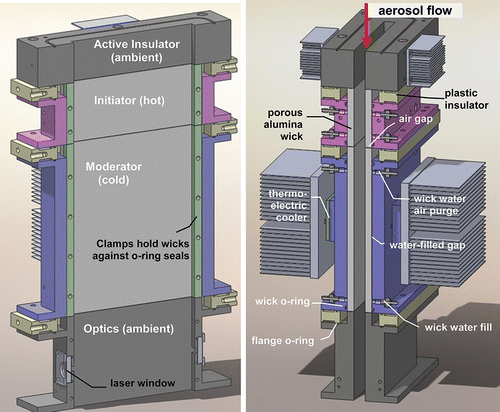
Figure 2. CAD image of the water condensation growth channel showing the Active Insulator, Initiator, Moderator, and Optics. Temperature control is provided by thermo-electric devices and cartridge heaters. Wicks are held in place by threaded clamps (green) and self-sealing bolts (not shown) and sealed by o-rings.

Figure 3. Experimental configuration (a) for measuring droplet size produced by the growth channel, and (b) for evaluation with monodispersed particles. CPC is a condensation particle counter; APS is TSI 3321 aerodynamic particle sizer; long DMA is TSI Model 3081 differential mobility analyzer.
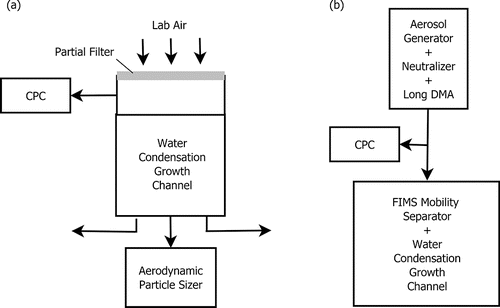
Figure 3. Experimental configuration (a) for measuring droplet size produced by the growth channel, and (b) for evaluation with monodispersed particles. CPC is a condensation particle counter; APS is TSI 3321 aerodynamic particle sizer; long DMA is TSI Model 3081 differential mobility analyzer.

Figure 4. Size spectra of droplets exiting the growth channel at an initiator temperature of 55°C at flow rates of 10, 13, and 16 L/min. Inlet temperature is 24°C; equilibrator temperature is 11–12°C.
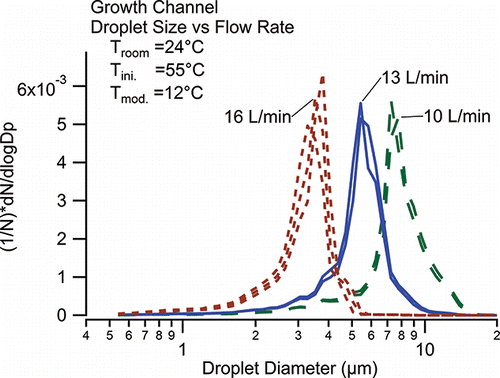
Figure 4. Size spectra of droplets exiting the growth channel at an initiator temperature of 55°C at flow rates of 10, 13, and 16 L/min. Inlet temperature is 24°C; equilibrator temperature is 11–12°C.

Figure 5. Images obtained from CCD of 100 nm, 65 nm, and 42 nm DMA classified NaCl particles in the prototype water-FIMS. Gray lines indicate the edges of the separation channel (i.e., the electrode surface). The ground plane, along which the particles are introduced at the top of the separator, is on the left; the high voltage electrode is on the right.
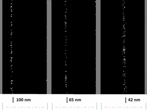
Figure 5. Images obtained from CCD of 100 nm, 65 nm, and 42 nm DMA classified NaCl particles in the prototype water-FIMS. Gray lines indicate the edges of the separation channel (i.e., the electrode surface). The ground plane, along which the particles are introduced at the top of the separator, is on the left; the high voltage electrode is on the right.

Figure 6. Histogram of particle concentrations vs. position in the mobility separator for 6 sizes of monodisperse sodium chloride aerosols. Aerosol and sheath flows were 0.3 L/min and 13 L/min, respectively. The mobility separator was operated at 700 V.
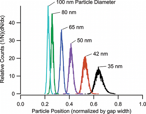
Figure 6. Histogram of particle concentrations vs. position in the mobility separator for 6 sizes of monodisperse sodium chloride aerosols. Aerosol and sheath flows were 0.3 L/min and 13 L/min, respectively. The mobility separator was operated at 700 V.

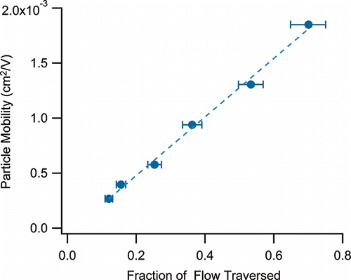
Figure 7. Particle mobility vs. fraction of flow traversed by the particle for the data of . Error bars are calculated from the peak width at half-height. A linear relationship is observed, as predicted by theory.

Figure 7. Particle mobility vs. fraction of flow traversed by the particle for the data of Figure 6. Error bars are calculated from the peak width at half-height. A linear relationship is observed, as predicted by theory.

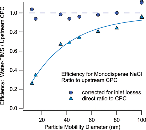
Figure 8. Particle number concentrations measured by water-FIMS as compared to a butanol-based ultrafine condensation particle counter operated in parallel.

Figure 8. Particle number concentrations measured by water-FIMS as compared to a butanol-based ultrafine condensation particle counter operated in parallel.
Supplemental material

UAST_1338338_Supplementary_Files.zip

Download Zip (1.1 MB)

Reprints and Corporate Permissions

Please note: Selecting permissions does not provide access to the full text of the article, please see our help page How do I view content?

To request a reprint or corporate permissions for this article, please click on the relevant link below:

Academic Permissions

Please note: Selecting permissions does not provide access to the full text of the article, please see our help page How do I view content?

Obtain permissions instantly via Rightslink by clicking on the button below:

If you are unable to obtain permissions via Rightslink, please complete and submit this Permissions form. For more information, please visit our Permissions help page.