Figures & data
Figure 1. The solution of a one-dimensional diffusion equation for x = 1 cm and t = 10 s. On the vertical axis is the concentration according to EquationEquation (2[2] ) and on the horizontal axis is the diffusion coefficient.
![Figure 1. The solution of a one-dimensional diffusion equation for x = 1 cm and t = 10 s. On the vertical axis is the concentration according to EquationEquation (2[2] ) and on the horizontal axis is the diffusion coefficient.](/cms/asset/83a6c343-d490-4c0d-a2aa-e19986fab378/uast_a_1367089_f0001_b.gif)
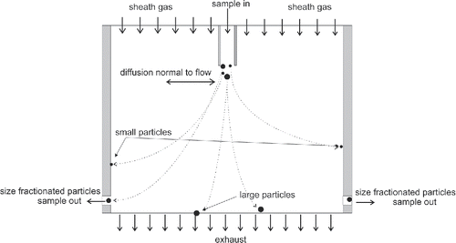
Figure 3. Illustration of the numerical model and its boundary conditions presented in EquationEquations (4[4] )–(7).
![Figure 3. Illustration of the numerical model and its boundary conditions presented in EquationEquations (4[4] )–(7).](/cms/asset/e23f33b2-c7c8-491f-b882-86b8dd495fcd/uast_a_1367089_f0003_b.gif)
Figure 4. (a) Theoretical DDA transmission functions for different sample to sheath flow ratios (solid lines), the charge fraction of singly charged particles in equilibrium (dashed line, Wiedensohler Citation1998), and the collected particle fraction for the second stage of a two-stage screen diffusion battery (gray line, Dubtsov et al. Citation2017). Numbers adjacent to curves represent the ratio of the sample to sheath flow. (b) Theoretical transmission functions for different flow ratios as a function of the diffusion coefficient for the DDA and a DMA. The DMA dimensions correspond to the TSI's Nano DMA, and the DDA parameters used in the model were the same as in Figure (a). The DMA transmission efficiency was calculated according to the theory presented by Stolzenburg (Citation1988).
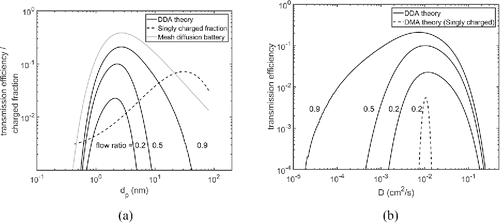
Figure 5. Concentration profiles in the half-cross section of the DDA for 2 nm (a), 5 nm (b), and 25 nm (c) particles. The sample flow rate is 0.32 lpm and sheath flow rate is 0.96 lpm. The concentration is normalized to the unity at the inlet.
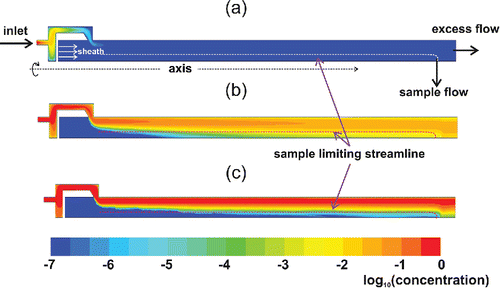
Figure 6. A schematic of the generation and measurement setup used to calibrate the DDA with monodisperse Ag particles.

Figure 7. Measured and CFD simulated transmission efficiency of the DDA for the sheath flow of 0.48 lpm and sample flow of 0.16 lpm.
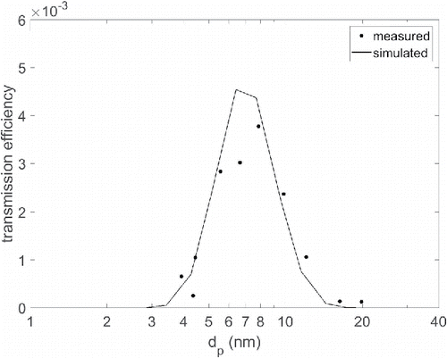
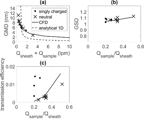
Figure 8. (a) Geometric mean diameter (GMD) of the output particle size distribution from the DDA as a function of the total flow rate (for Qsample/Qsheat = 0.33). (b) Geometric standard deviation (GSD) of the output particle size distribution as a function of the aerosol to sheath flow ratio. (c) Transmission efficiency as a function of the sample to sheath flow ratio. Different symbols represent the charge state of particles and the solid and the dashed lines represent the CFD and analytical model results, respectively. The analytical model was calculated based on Equation (3).
