1,422
Views
3
CrossRef citations to date
0
Altmetric
Original Articles

Using partial flow dilution to measure PM mass emissions from light-duty vehicles

, &
Pages 136-145 | Received 06 Jun 2017, Accepted 25 Sep 2017, Published online: 23 Oct 2017

Figures & data

Figure 1. Second by second regression of ultrasonic versus CO2 tracer measurements of vehicle exhaust flow rate over the combined FTP + US06 drive cycle. The inset compares the time response of the ultrasonic flow meter to the CO2 tracer method over a 45 s portion of the US06 cycle.
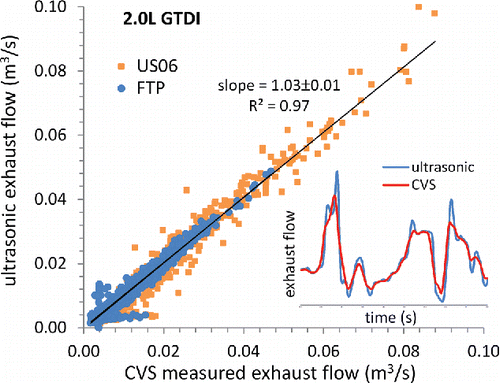
Figure 1. Second by second regression of ultrasonic versus CO2 tracer measurements of vehicle exhaust flow rate over the combined FTP + US06 drive cycle. The inset compares the time response of the ultrasonic flow meter to the CO2 tracer method over a 45 s portion of the US06 cycle.

Figure 2. Proportionality of sample flow rate into the PFD versus the 2.0 L GTDI vehicle exhaust flow rate for each phase of the FTP + US06 cycle.
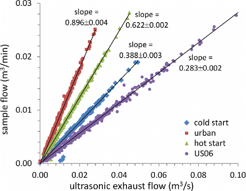
Figure 2. Proportionality of sample flow rate into the PFD versus the 2.0 L GTDI vehicle exhaust flow rate for each phase of the FTP + US06 cycle.

Figure 3. The main graph displays regressions of gravimetric PM mass emissions measured via PFD versus CVS tunnel. Data from 15 tests in cell A and 18 tests in cell B are plotted separately for each phase of the FTP cycle. The inset provides an expanded view of PM emissions in the 3 mg/mi range. The lower graph displays the residuals.
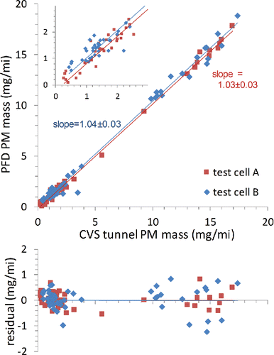
Figure 3. The main graph displays regressions of gravimetric PM mass emissions measured via PFD versus CVS tunnel. Data from 15 tests in cell A and 18 tests in cell B are plotted separately for each phase of the FTP cycle. The inset provides an expanded view of PM emissions in the 3 mg/mi range. The lower graph displays the residuals.

Figure 4. PM mass measured by PFD, in the CVS tunnel, and soot measured photoacoustically from 17 repeat FTP tests of the 2012 GDI test vehicle at two sites. The panels show FTP weighted average (top left) and phase by phase PM emissions rates. Note the different vertical scale for the cold start data. Lines are to help distinguish test-to-test trends between the different measurement methods.
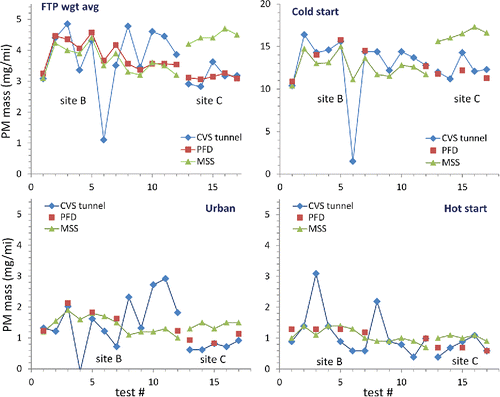
Figure 4. PM mass measured by PFD, in the CVS tunnel, and soot measured photoacoustically from 17 repeat FTP tests of the 2012 GDI test vehicle at two sites. The panels show FTP weighted average (top left) and phase by phase PM emissions rates. Note the different vertical scale for the cold start data. Lines are to help distinguish test-to-test trends between the different measurement methods.
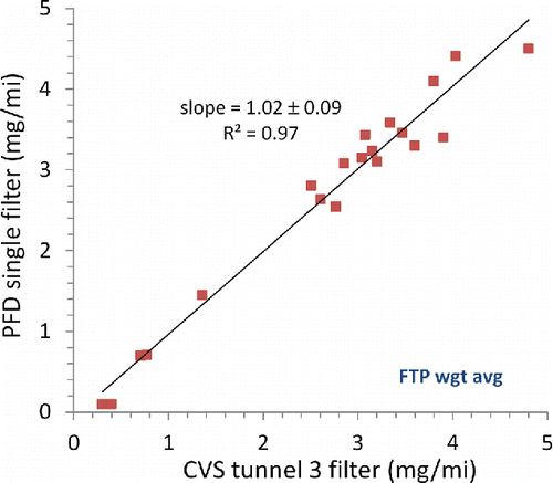
Figure 5. Single versus three filter measurements of FTP weighted average PM mass emissions.

Figure 5. Single versus three filter measurements of FTP weighted average PM mass emissions.

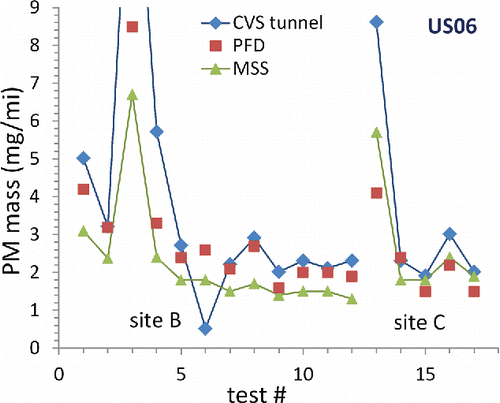
Figure 6. US06 cycle PM mass emissions recorded via PFD versus CVS tunnel and MSS. The lines are to help distinguish test-to-test trends amongst the different measurement methods.

Figure 6. US06 cycle PM mass emissions recorded via PFD versus CVS tunnel and MSS. The lines are to help distinguish test-to-test trends amongst the different measurement methods.

Reprints and Corporate Permissions

Please note: Selecting permissions does not provide access to the full text of the article, please see our help page How do I view content?

To request a reprint or corporate permissions for this article, please click on the relevant link below:

Academic Permissions

Please note: Selecting permissions does not provide access to the full text of the article, please see our help page How do I view content?

Obtain permissions instantly via Rightslink by clicking on the button below:

If you are unable to obtain permissions via Rightslink, please complete and submit this Permissions form. For more information, please visit our Permissions help page.