1,046
Views
3
CrossRef citations to date
0
Altmetric
Articles

Continuous flow hygroscopicity-resolved relaxed eddy accumulation (Hy-Res REA) method of measuring size-resolved sodium chloride particle fluxes

ORCID Icon, , , , ORCID Icon, , , & show all
Pages 433-450 | Received 25 Aug 2017, Accepted 26 Dec 2017, Published online: 23 Jan 2018

Figures & data

Figure 1. Schematic of the aerosol generation and sampling facility (adapted from the U.S. EPA National Homeland Security Research Center). Arrows indicate the locations of the large electrical fan and aerosol generators.
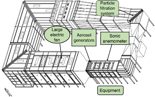
Figure 1. Schematic of the aerosol generation and sampling facility (adapted from the U.S. EPA National Homeland Security Research Center). Arrows indicate the locations of the large electrical fan and aerosol generators.

Figure 2. Schematic of the experimental setup of NaCl particle fluxes: (a) total particle EC flux mode, (b) total particle REA flux mode, (c) particle size selected (at 144 nm) REA flux mode, and (d) particle size selected (at 144 nm) hygroscopicity-resolved REA flux mode.
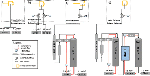
Figure 2. Schematic of the experimental setup of NaCl particle fluxes: (a) total particle EC flux mode, (b) total particle REA flux mode, (c) particle size selected (at 144 nm) REA flux mode, and (d) particle size selected (at 144 nm) hygroscopicity-resolved REA flux mode.

Figure 3. Schematics of the experimental setup used for conducting the random valve tests.

Figure 3. Schematics of the experimental setup used for conducting the random valve tests.

Figure 4. Size selected valve transmission fractions due to air dilution and particle loss inside the 3-way solenoid (a) valve-1 and (b) valve-2.
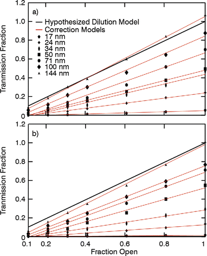
Figure 4. Size selected valve transmission fractions due to air dilution and particle loss inside the 3-way solenoid (a) valve-1 and (b) valve-2.

Figure 5. Example of NaCl particle number size distribution inside the ATF wind tunnel. The size distribution was corrected for the particle losses in the valves.
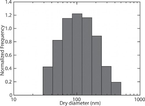
Figure 5. Example of NaCl particle number size distribution inside the ATF wind tunnel. The size distribution was corrected for the particle losses in the valves.

Figure 6. Time series of (a) vertical velocity and (b) total NaCl particle concentration for the measurement Mode 1. Time series of (b) vertical velocity and (c) 144 nm sized NaCl particle concentration for the measurement Mode 2.
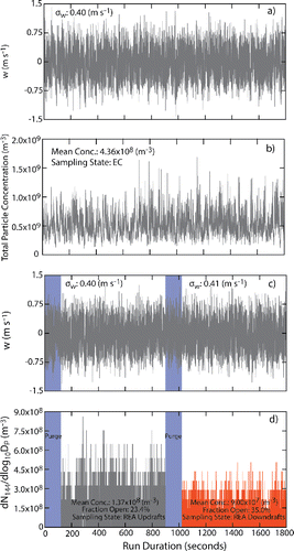
Figure 6. Time series of (a) vertical velocity and (b) total NaCl particle concentration for the measurement Mode 1. Time series of (b) vertical velocity and (c) 144 nm sized NaCl particle concentration for the measurement Mode 2.

Figure 7. A two-dimensional frequency distribution of NaCl particle number concentration fluctuations (c') versus vertical wind velocity (w') fluctuations averaged over 15-min period. Both quantities are normalized and nondimensionalized through dividing by their respective standard deviations. Vertical dashed lines show the REA sampling threshold of |w0| /σw = 0.8.
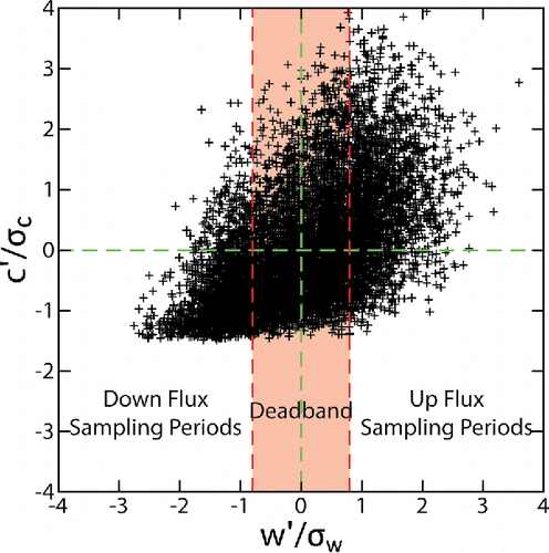
Figure 7. A two-dimensional frequency distribution of NaCl particle number concentration fluctuations (c') versus vertical wind velocity (w') fluctuations averaged over 15-min period. Both quantities are normalized and nondimensionalized through dividing by their respective standard deviations. Vertical dashed lines show the REA sampling threshold of |w0| /σw = 0.8.

Figure 8. Example power density spectra of (a) temperature, (b) horizontal velocity, (c) vertical velocity, and (d) NaCl particle concentration. Black lines correspond to mean spectra (n = 23), the dark gray shaded regions correspond to the respective 5th and 95th confidence intervals for the mean spectra, and the light gray shaded regions correspond with 5th and 95th quantiles for the mean spectra. The dashed (red) line shows −5/3 slope characteristic of turbulence spectra at higher frequencies.
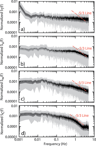
Figure 8. Example power density spectra of (a) temperature, (b) horizontal velocity, (c) vertical velocity, and (d) NaCl particle concentration. Black lines correspond to mean spectra (n = 23), the dark gray shaded regions correspond to the respective 5th and 95th confidence intervals for the mean spectra, and the light gray shaded regions correspond with 5th and 95th quantiles for the mean spectra. The dashed (red) line shows −5/3 slope characteristic of turbulence spectra at higher frequencies.

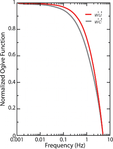
Figure 9. 15-min averaged ogive curves for w' u' and w' c' covariancees.

Figure 9. 15-min averaged ogive curves for w' u' and w' c' covariancees.

Figure 10. Total measured NaCl particle fluxes using EC and REA methods (a) before and (b) after the correction, respectively.
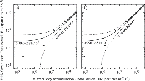
Figure 10. Total measured NaCl particle fluxes using EC and REA methods (a) before and (b) after the correction, respectively.
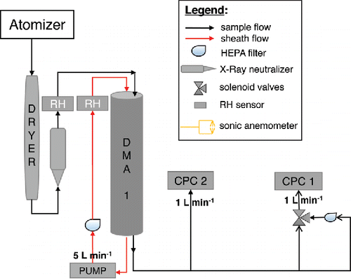
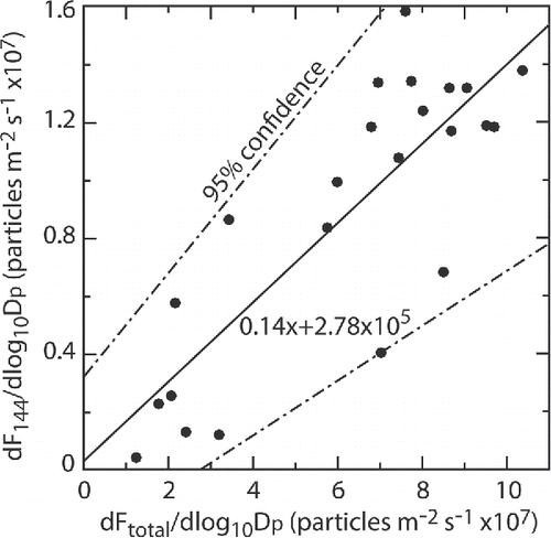
Figure 11. NaCl particle size selected (144 nm) REA flux plotted against EC flux of total NaCl particles.

Figure 11. NaCl particle size selected (144 nm) REA flux plotted against EC flux of total NaCl particles.

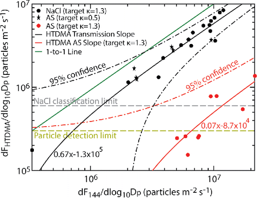
Figure 12. Hygroscopicity-resolved REA fluxes of 144 nm sized particles plotted against REA fluxes of 144 nm sized particles.

Figure 12. Hygroscopicity-resolved REA fluxes of 144 nm sized particles plotted against REA fluxes of 144 nm sized particles.
Supplemental material

Supplementary.docx

Download MS Word (360.5 KB)

Reprints and Corporate Permissions

Please note: Selecting permissions does not provide access to the full text of the article, please see our help page How do I view content?

To request a reprint or corporate permissions for this article, please click on the relevant link below:

Academic Permissions

Please note: Selecting permissions does not provide access to the full text of the article, please see our help page How do I view content?

Obtain permissions instantly via Rightslink by clicking on the button below:

If you are unable to obtain permissions via Rightslink, please complete and submit this Permissions form. For more information, please visit our Permissions help page.